How to mill and drill double sided PCB using transformations and warp
MILLING DOUBLE SIDED PCB’S WITH CNC USB CONTROLLERS
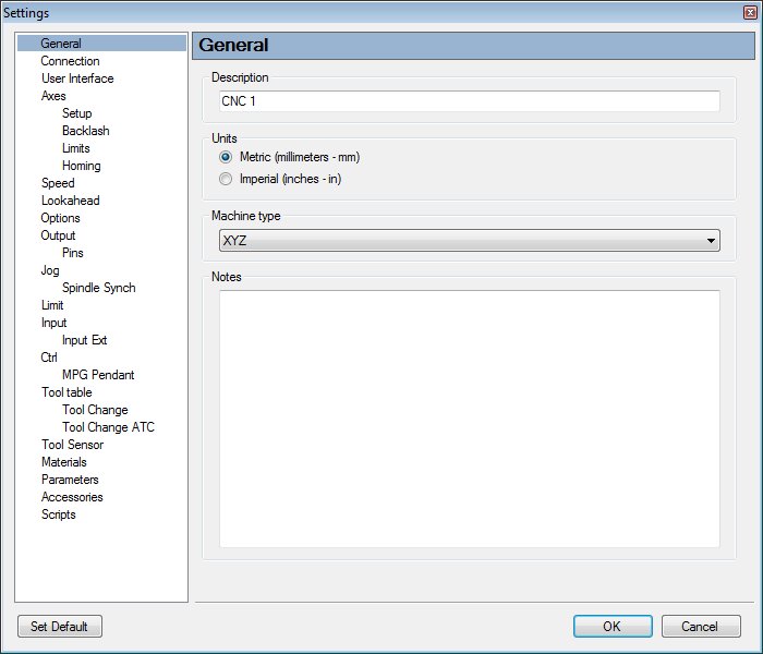
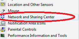
This tutorial will help you with production of double-sided PCB’s with your CNC machine.
Before you start, please be sure that machine is properly set-up and calibrated. Gerber and drill files should be generated with correct parameters.
Since tutorial for single sided PCB’s already describes the gerber and drill files import parameters in detail, we suggest that you read that tutorial first to clear out some facts regarding parameters and procedure itself.
Because we will capture reference points coordinates with a camera, camera offset needs to be set.
Tutorial for machine setup:
Machine setup tutorial
Tutorial for SPU configuration:
SPU tutorial
Tutorial for single sided PCB:
PCB tutorial
Tutorial for calibrating camera offset:
Camera offset
Steps for milling a double-sided PCB are as follows:
TOP Layer
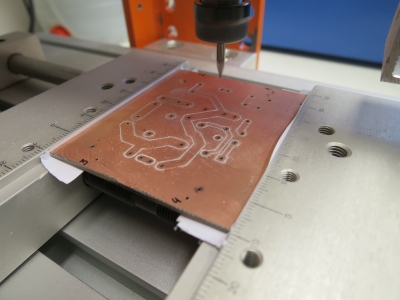
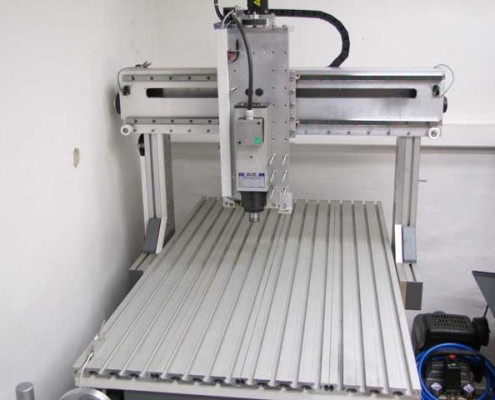
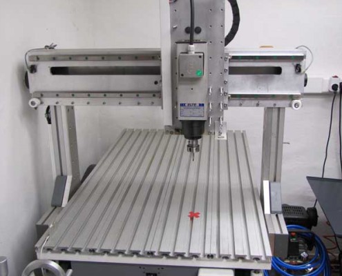
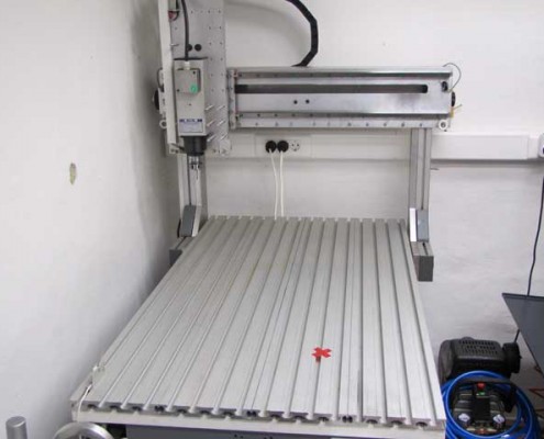
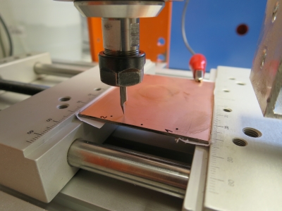
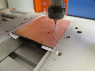
1.) Mount copper board to machine table
2.) Set “Current XY” offset
3.) Drill and store reference points
4.) Measure the surface of the board (“Warp”)
5.) Import “Gerber TOP” file
6.) Apply “Warp”
7.) Mill TOP layer
BOTTOM Layer
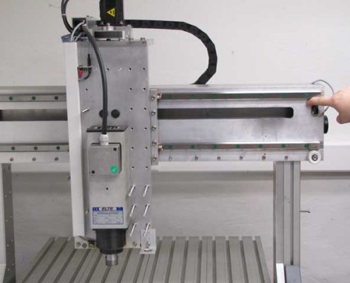
1.) Turn around the copper board and mount it to machine table
2.) Set „Current XY“ offset
3.) Capture reference points with camera
4.) Measure the surface of the board (“Warp”)
5.) Import „NC drill“ file
6.) Use transformation from points
7.) Drill holes
8.) Import BOTTOM layer gerber
9.) Use transformation from points
10.)Apply „Warp“
11.)Mill BOTTOM layer
12.)Clear Copper
TOP layer
1.) Mount copper board to machine table
You can use a vise, double sided tape, vacuum board or even screws to attach the board on the machine table. Whatever works for you best.
2.) Set “Current XY” offset
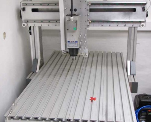
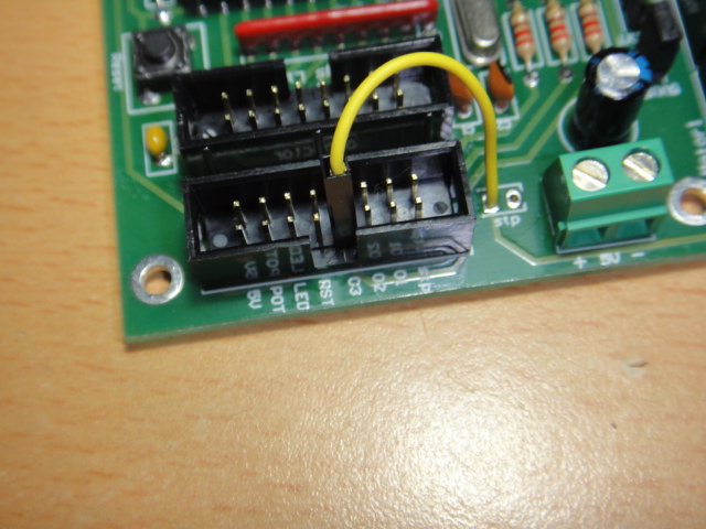
The copper board should always be little bigger than the actual PCB layout. Since we are making a double sided PCB, we will use reference points for the needs of transformation, therefore we will need slightly bigger board.
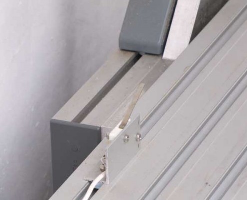
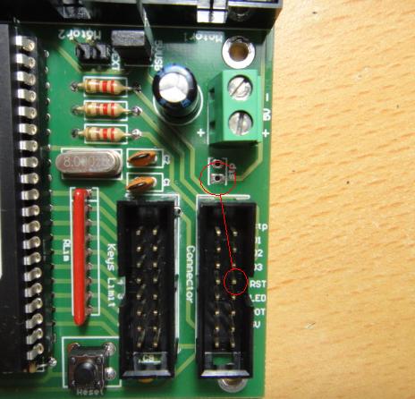
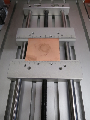
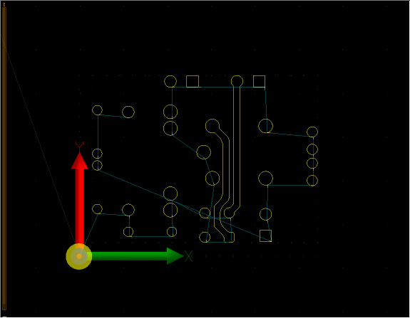
Reference points should be drilled at such coordinates where they would not interfere with milling, drilling and measuring of a surface. So when you will be setting offset XY=0 position, take into consideration where reference points will be drilled and where actual PCB milling will take its place in relation to XY=0. For this tutorial we positioned reference points on the outskirts of the copper board(see image below).
Working XY offset should be set in the origin of cross-hatching area(see image below). This area represents the PCB layout as also a surface of measuring area.

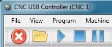
To set working offset from machine menu: “Machine/Offset/Current/XY” or click on the icon from toolbar.
3.) Drill and store reference points
As already mentioned earlier, reference points should be positioned somewhere on the board where they would not distract the drilling/milling process.
Reference points are basically coordinates which are later used in transformation process, where bottom layer is transformed so that is “synced”(mirrored and aligned) with the top layer.
Reference points coordinates will be stored and later loaded into transformation matrix table.
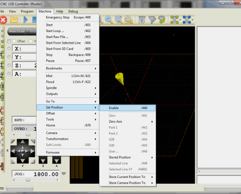
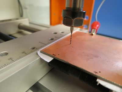
Storing and drilling reference points:
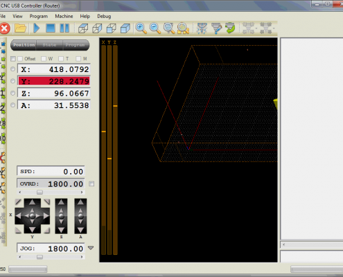
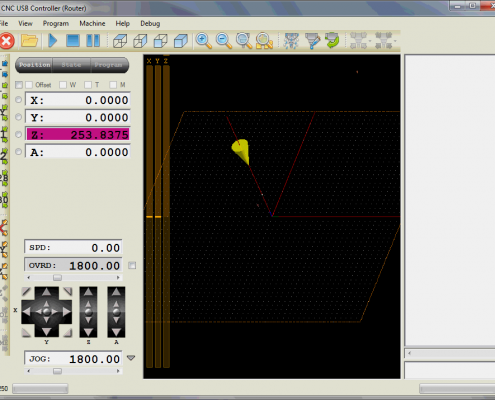
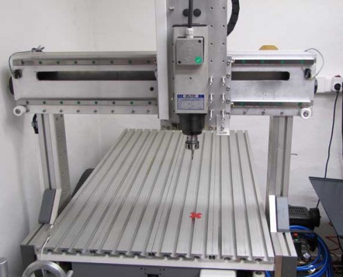
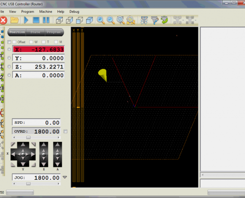
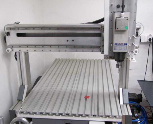
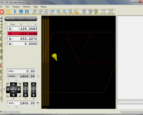
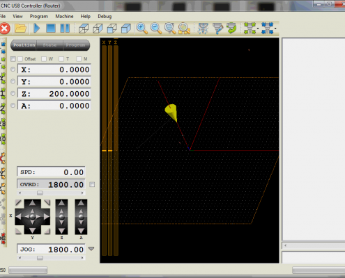
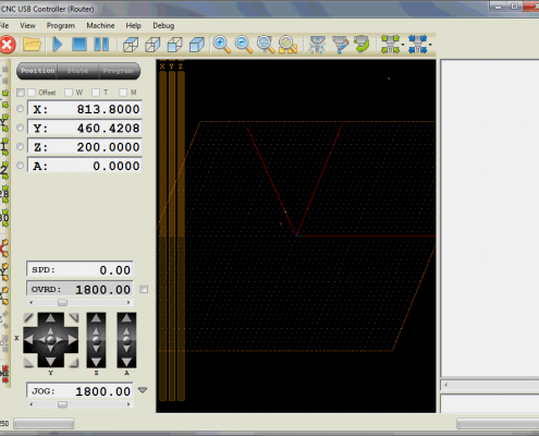
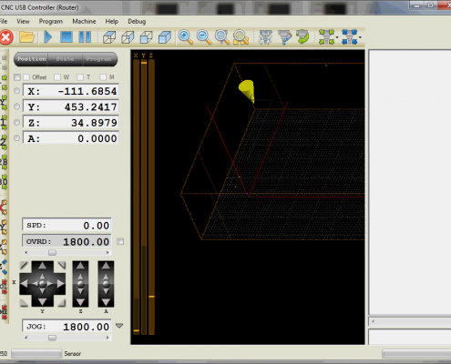
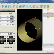
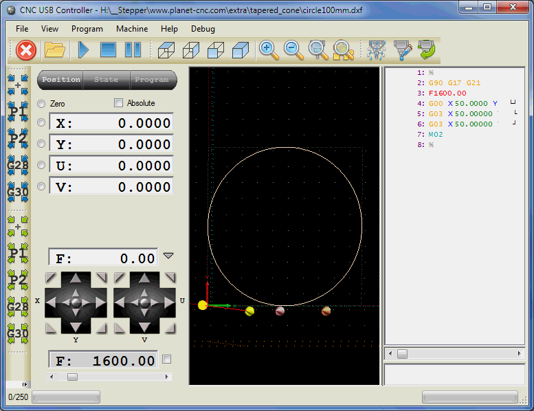
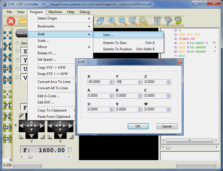
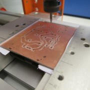
-Insert coordinate of reference point into MDI and hit enter, machine will move to entered position:
![]()
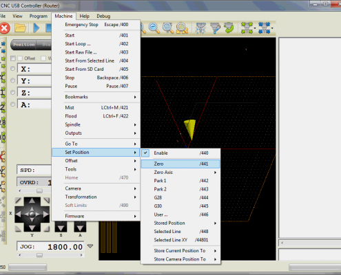
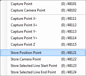
-When machine reaches position you store it with:“Machine/Capture & Measure Points/Capture/Store Position Point”:
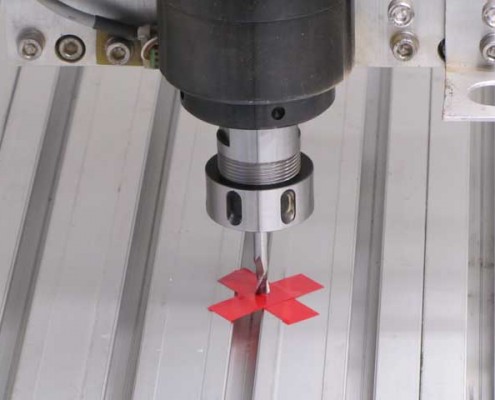
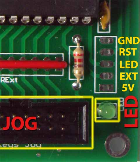
-Manually drill the hole by jogging Z axis with arrow keys(SW, PC keyboard or jogging keyboard)
-Mark drilled hole with a sequence number using a pen.
Follow these steps for each reference point, respectively.
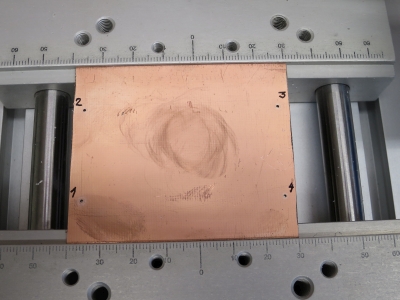
My reference points(used for this tutorial):
1.) -3 , 5
2.) -3 , 35
3.) 60 , 35
4.) 60 , 5
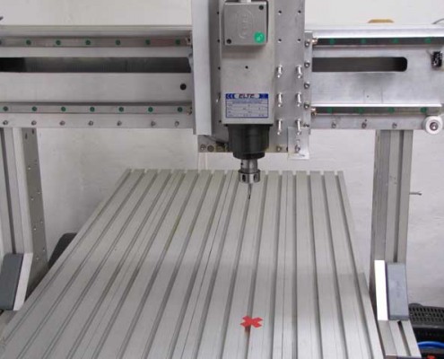
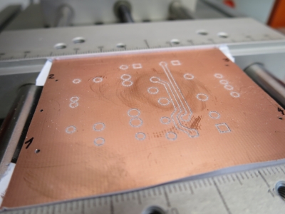
Drilled and marked reference points:
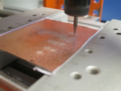
4.) Measure the surface of the board (“Warp”)
Already smallest PCB surface height irregularities can create bad results in terms of milling. That’s why we will use “Warp” feature which will compensate different surface heights of the board within the milling process.
More on how to set measuring parameters and about procedure itself follow this link: Warp tutorial
NOTE:Do not apply Warp, Warp is applied in Step 6. Also make sure all previous points are cleared, you can do that by clicking: “Machine/Capture&Measure Points/Clear/Clear Points Z”.
Measuring the surface of PCB board:
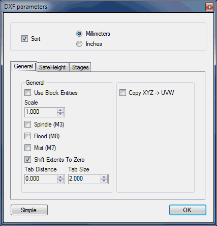
5.) Import “Gerber TOP” file
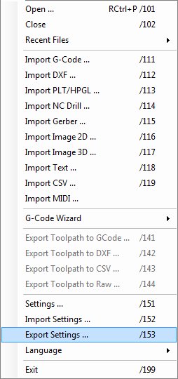
Click:“File/Import gerber”
How to configure gerber milling parameters follow this link: Gerber import tutorial
6.) Apply “Warp”
Previously measured surfaced points will now be used for “warping” the toolpath.
Click: „Program/Advanced/Warp“ to apply Warp.
7.) Mill TOP layer
BOTTOM layer
1.) Turn around the copper board
Mount it to machine table and mark each reference point with correct sequence number using pen.
The sequence number of bottom reference point is the same as it is for its corresponding top reference point.
2.) Set “Current XY” offset
Like already mentioned in the second step of previous chapter(see image), consider the PCB layout area and surface measuring area when setting XY offset.You don’t need to be exact, use approximate position for XY=0.Transformation will make sure that bottom and top layer will fit perfectly.
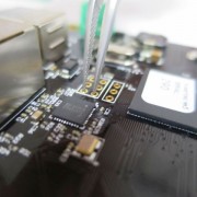
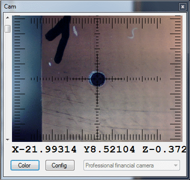
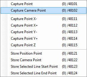
3.) Capture reference points with camera
Capture all coordinates of drilled holes using camera with “Machine/Capture & Measure Points/Capture/Capture Camera Point”.
When capturing reference point coordinates you must follow the same sequence as for drilling. Follow the marks on bottom side that you made earlier (1.,2.,..).
To display camera view click: „Machine/Camera/Show Camera“
4.) Measure the surface of the board (“Warp”)
More on how to set measuring parameters and about procedure itself follow this link: Warp tutorial
NOTE:Do not apply Warp, Warp is applied in Step 10. Also make sure all previous points are cleared, you can do that by clicking: “Machine/Capture&Measure Points/Clear/Clear Points Z”.
5.)Import Drill file
Drill file is a g-code program for drilling holes of a PCB. Now, we could drill holes already when board was prepared for milling a top layer, but since drilled holes would impede the measuring process of the bottom surface, we will drill them after that.
Click:“File/Import NC Drill”
On how to configure drill parameters follow this link: Gerber import tutorial;Step 4
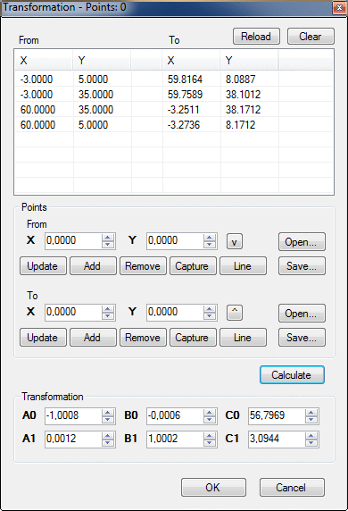
6.) Use transformation from points
Because we turned over the copper board, our drill toolpath now needs to be mirrored. We will achieve mirrored toolpath by transforming it. After transformation, drill toolpath will be correctly mirrored and aligned with the TOP layer.
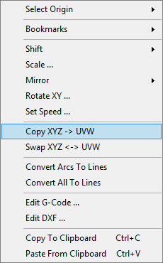
Use “Program/Advanced/Transform from points“:.
You will notice that the table is already populated with coordinates. Previously stored reference points have populated „From“ group of points and camera captured points populated „To“ group of points.
Apply transformation(click “Calculate” button):
7.) Drill holes
If everything is OK, we can proceed with drilling holes.
8.)Import BOTTOM layer gerber
Click:“File/Import gerber”
On how to configure milling parameters follow this link:Gerber import tutorial
9.) Use transformation from points
Because we turned over the copper board, our mill toolpath now needs to be mirrored. We will achieve mirrored toolpath by transforming it. After transformation, mill toolpath will be correctly mirrored and aligned with the TOP layer.
This procedure is the same as for drilling holes only now bottom layer gerber file is used.
Use “Program/Advanced/Transform from points“:
All “From” and “To” group of points should already be loaded into the table.
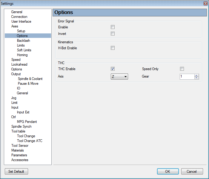
10.) Apply “Warp”
Click: „Program/Advanced/Warp“ to apply Warp.
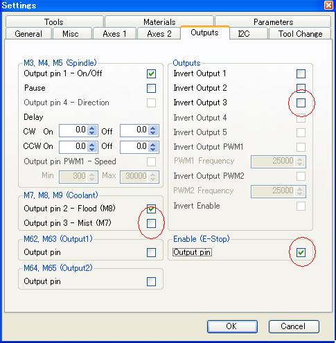
We measured the bottom surface with a drill bit, and while we did perform a “Measure Grid Z Offset” to set Z0 of the board, we changed our tool from drilling bit to a milling bit and therefore “Measure Grid Z Offset” point is now irrelevant so we need to measure working Z offset again.