How to import DXF files?
DXF FILE IMPORT CONFIGURATION
Using DXF files is probably most common way to start with machining your first CAD design with your CNC machine.
This short tutorial is made to show you how to configure your imported DXF file in different scenarios. Here are some short examples
on how to configure your DXF files for different scenarios, so that you can get satisfying results on your machine as soon as possible.
We start by clicking File/Import/DXF.
Import user dialog will apear:
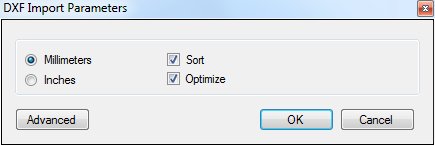
Since DXF files have no embedded units, you must define measurement units. Millimeters or inches can be specified.
If you click Advanced, you will be able to set parameters in all three tabs: General, Safe Height and Stages:
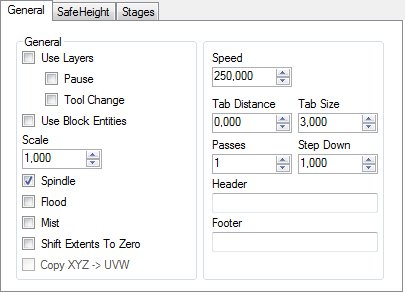
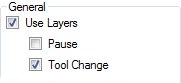
General Tab
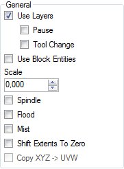
Use layers
Elements within DXF files are usually grouped in layers. If you choose to use them, you will be able to see certain layers name
in generated G-code window. Use layers feature also allows you to generate Pause and make Tool Change procedure in-between layers.
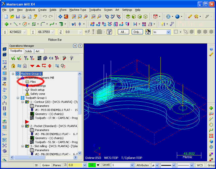
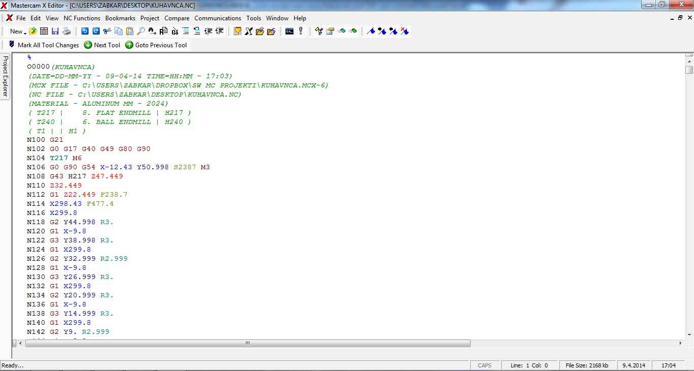
If your elements are given default layer names, you are able to see these layer names in G-code window. Specific layers name will
appear in the beginning of layers corresponded G-code. This way you can make your generated G-code slightly more transparent.
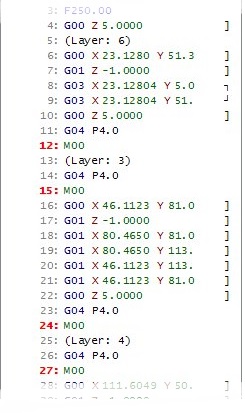
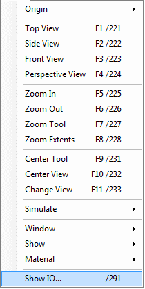
From picture above, you can clearly see where each layers corresponded G-code begins with execution.
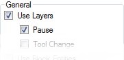
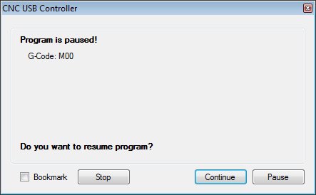
Use pause
Pause will occur at the beginning of specified layers G-code. User dialog will remind you that ‘Pause’ has been generated
and to resume program you must click Continue button.
Tool change
If you want to change tools between elements during your machine job, you can use tool change feature.
Tool change will occur at the beginning of specified layers G-code.
Note: Tool change must take place at its designated coordinates. Tool Change coordinates can be set among
other parameters referring to Tool Change in: File/Settings/Tool Change
Tab
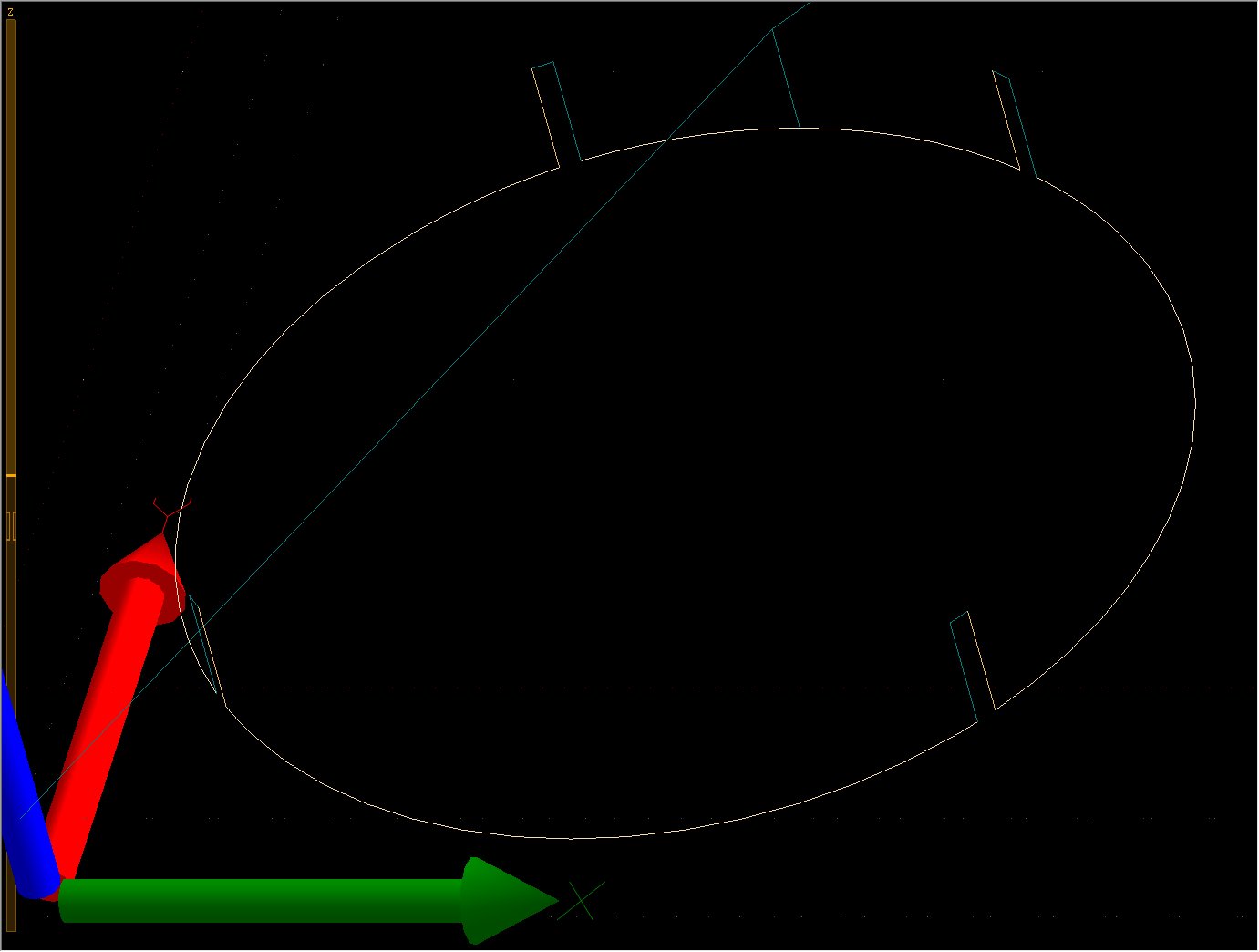
If your work piece doesn’t need to be cut-ed out completely and , you can use tabs to hold the piece in place.
Define length of tab with Tab Size and the distance between two tabs with Tab Distance.
![]()
You can see that Tab Size is the un-milled part of toolpath and Tab Distance is where milling will be applied.
Passes and Step Down
With Passes and Step Down you are able to define number of passes that machine will do over generated toolpath
at defined depth increment of plunge per pass.
![]()
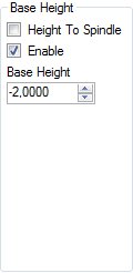
If surface of your working piece is set to be current Z offset, then value of Base Height will be the depth of machines first plunge move.
This is set in Safe Height tab under Base Height.
E.g.: If you want to cut material of thickness 10mm, and you want to cut it in 5 passes, you could set:
Passes: 5 and Step down: 2.000. What will happen is this: Machine will cut over generated toolpath in 5 passes total.
For each pass machine will plunge for 2mm.
Output control
Outputs ‘Spindle’, ‘Mist’ and ‘Flood’ can be turned ON and OFF in specified moments of tool-path milling process.
How outputs will be controlled depends on what type of cutting will be applied, what materials will be used etc.
Therefore you can set at which point in the milling process outputs would be turned ON/OFF using DXF import dialog.
You can set output ON/OFF control in different tabs of DXF import dialog. It can done in General tab, Safe Height tab or Stages tab.
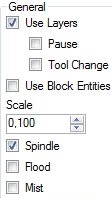
General tab
If outputs need to be turned ON at the beginning of milling process and turned OFF at the end of milling process, enable ‘Spindle’, ‘Flood’ or ‘Mist’ checkbox in General tab.
Specified outputs ‘ON’ G-code ‘M03’ will be generated at the beginning of toolpath, and specified output ‘OFF’ G-code ‘M05’ will be generated at the end of toolpath.
Safe Height Tab
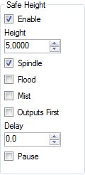
If traverse moves of your machine need to be at certain height, you enable and define this in Safe Height tab.
Enabled output will be turned ON at Safe Height before downward plunge move, and turned OFF at ‘Safe Height’ after downward plunge.
Stages Tab
If you need to turn outputs ON at certain heights you can use Stages feature. This comes very useful if you will be using plasma CNC cutting machine.
When stages are enabled, certain elements machining is divided in stages. Height of stage is where desired output will be turned ON.
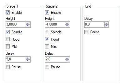
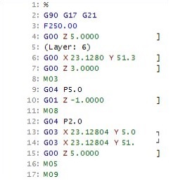
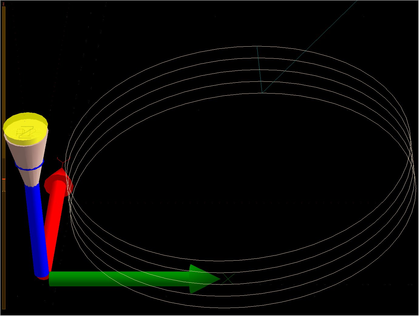
Stage configuration from picture above will result on CNC machine as:
Elements machining will be divided in two stages. If you have Safe height enabled and set (this is done in Safe height tab),then machine will make downward plunge move
from safe height,it will turn ON ‘Spindle’ output at height 3, wait for 5 seconds (Delay of stage 1)and continue with downward plunge move.
At -1 height, ‘Flood’ output will be turned ‘ON’, machine will wait for another 2 seconds (Delay of stage 2) and continue with the rest of elements toolpath. When milling
of toolpath is finished, both outputs will be turned ‘OFF’ at safe height.
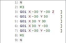
Generated G-code for current Stage setup looks like this: