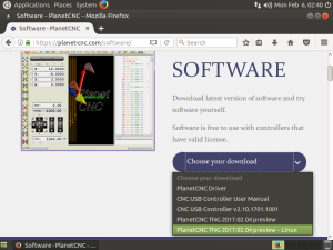
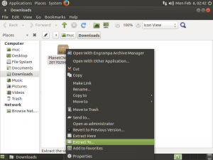
How to measure tool offset with fixed tool sensor in PlanetCNC TNG software
This tutorial will explain how to correctly use Tool Offset / Measure feature with fixed tool sensor using PlanetCNC TNG software and PlanetCNC motion controllers.
Fixed tool sensor
For fixed tool sensor we can use a dedicated tool measuring switch or, most basic solution, a standard micro switch fixed to machine table.
When tool activates tool sensor, controllers corresponding input is activated and software sets new tool offset value.
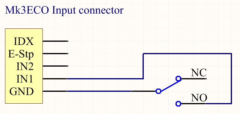
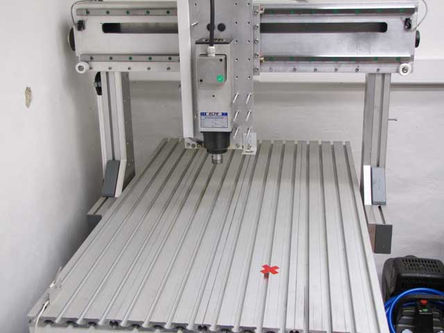
Example of fixed tool sensor used with Mk3 controller:
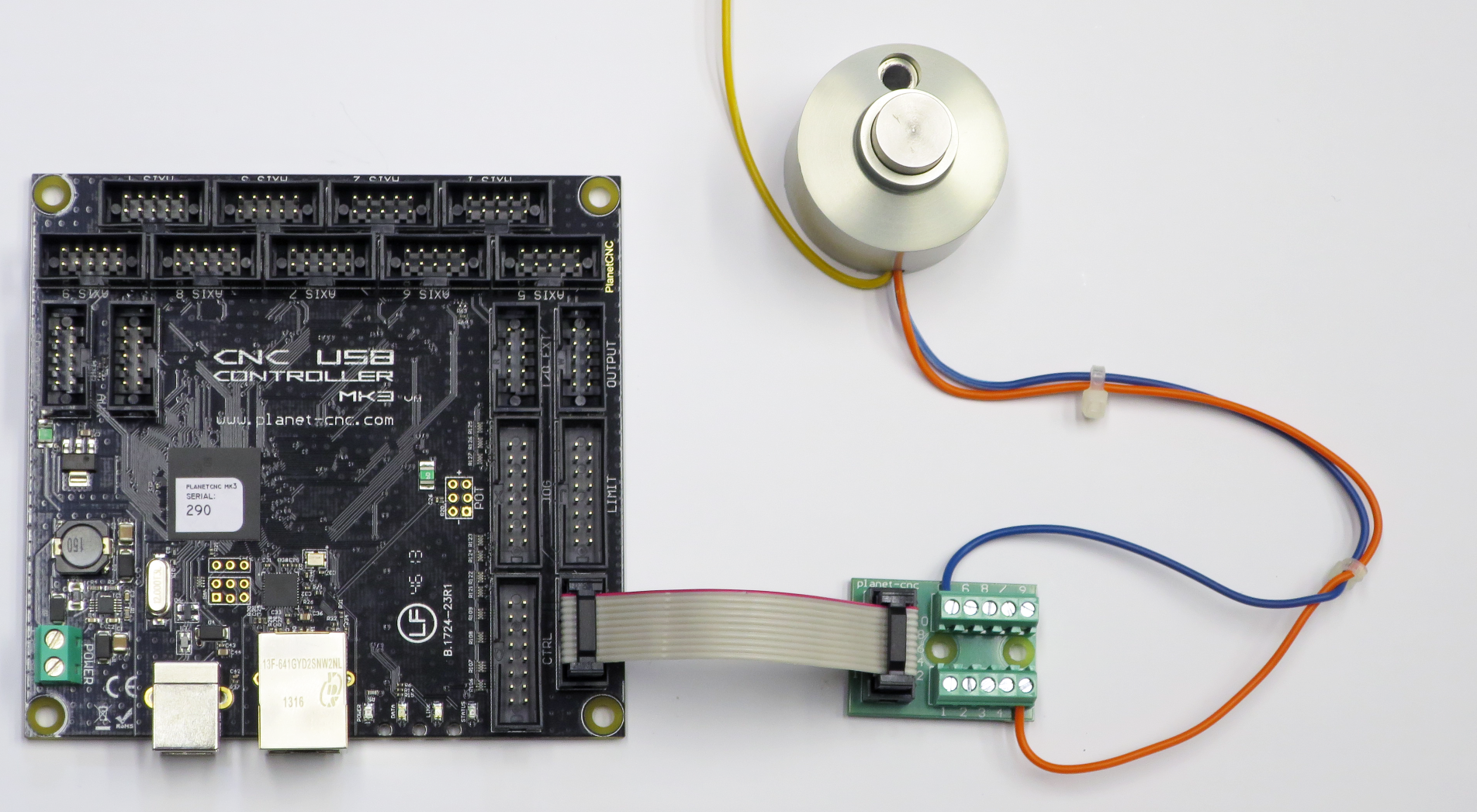
Connecting fixed sensor with PlanetCNC motion controller
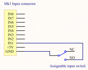
MK3 controller:
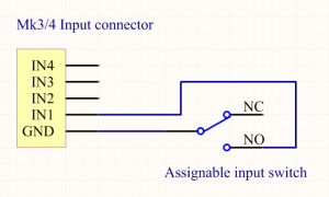
Mk3/4 controller:
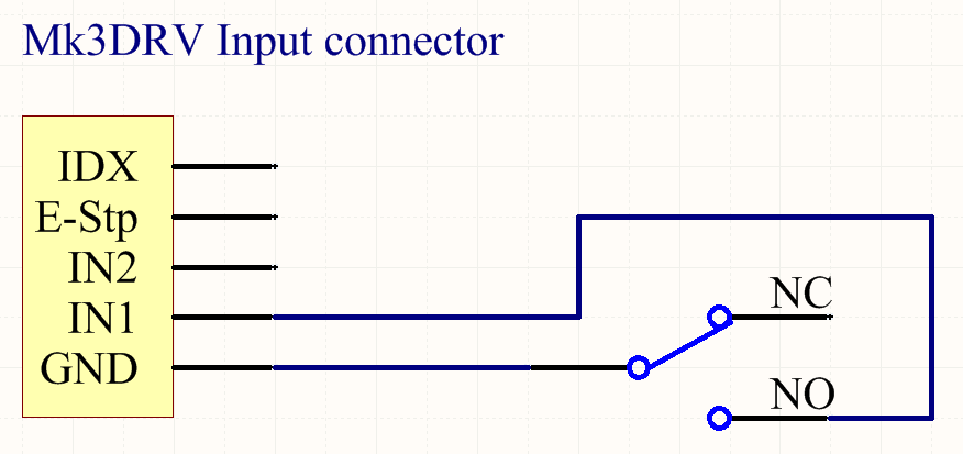
MK3DRV controller:
MK3ECO controller:
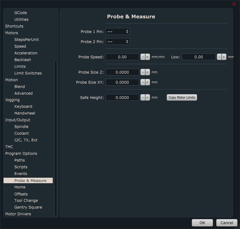
Configuring fixed tool sensor in PlanetCNC TNG software
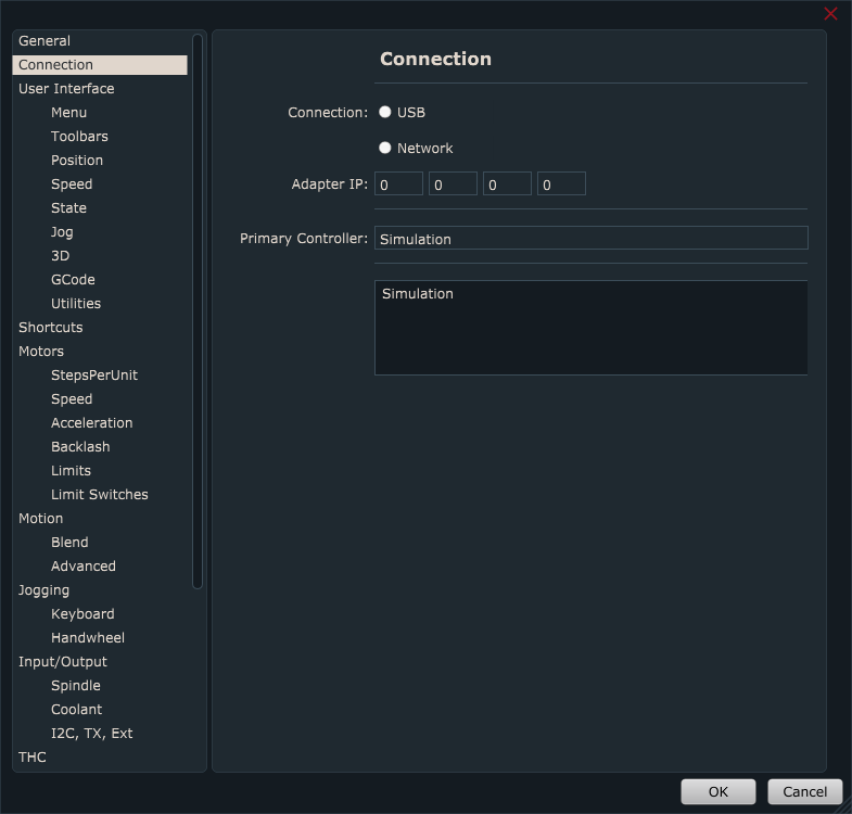
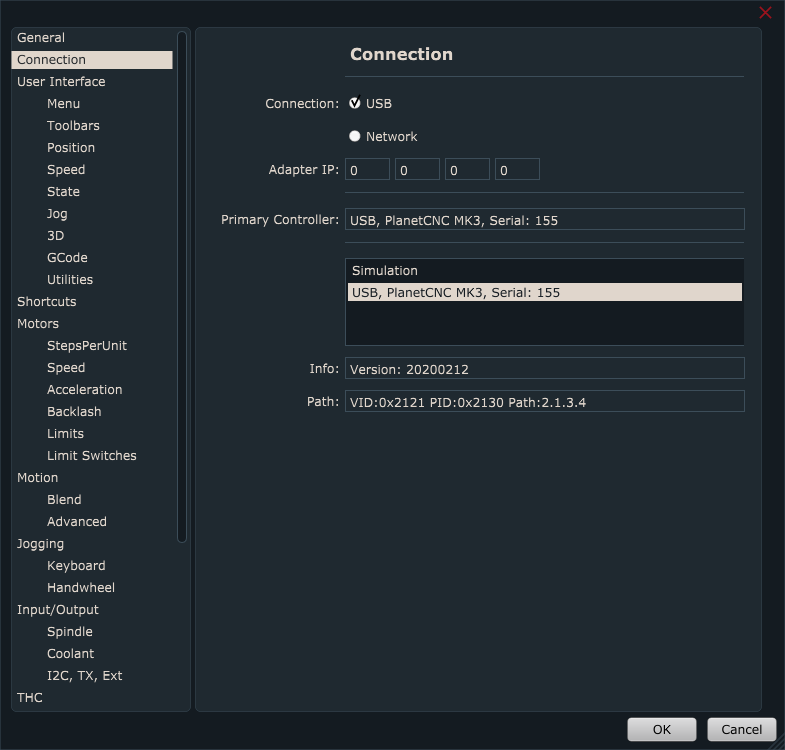
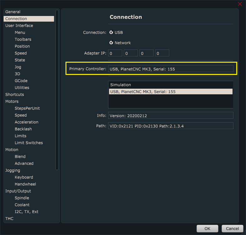
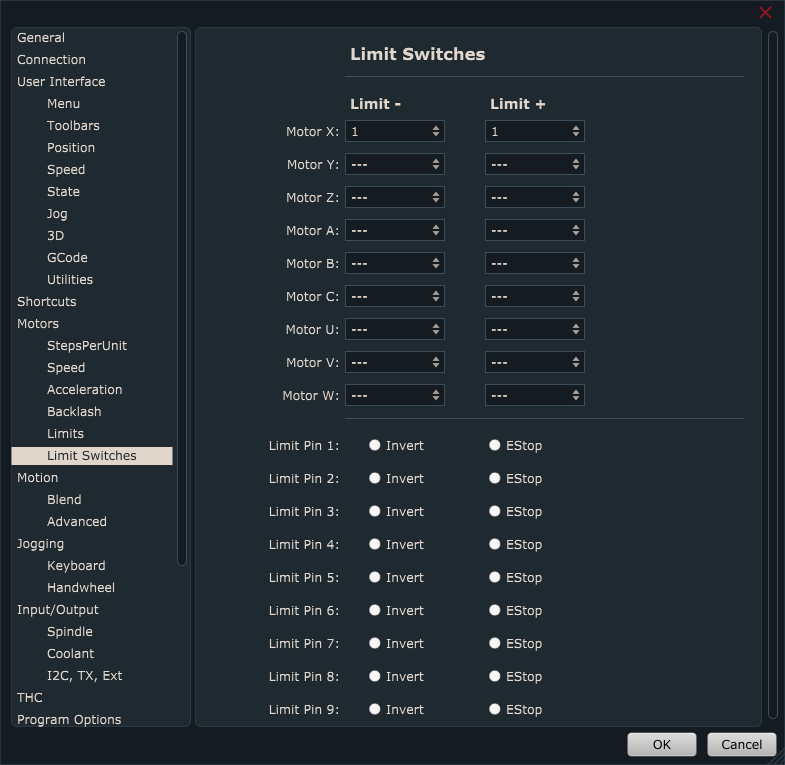
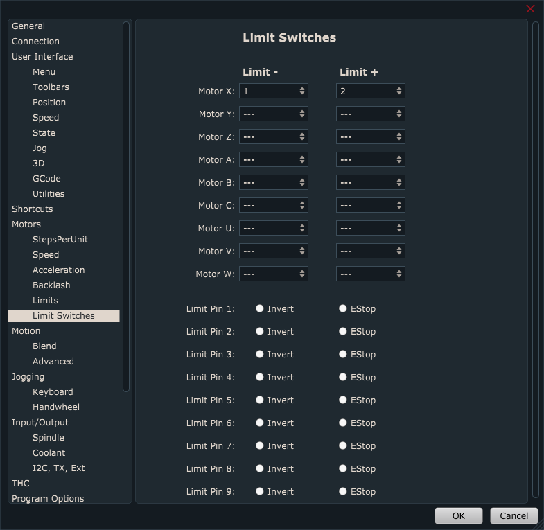
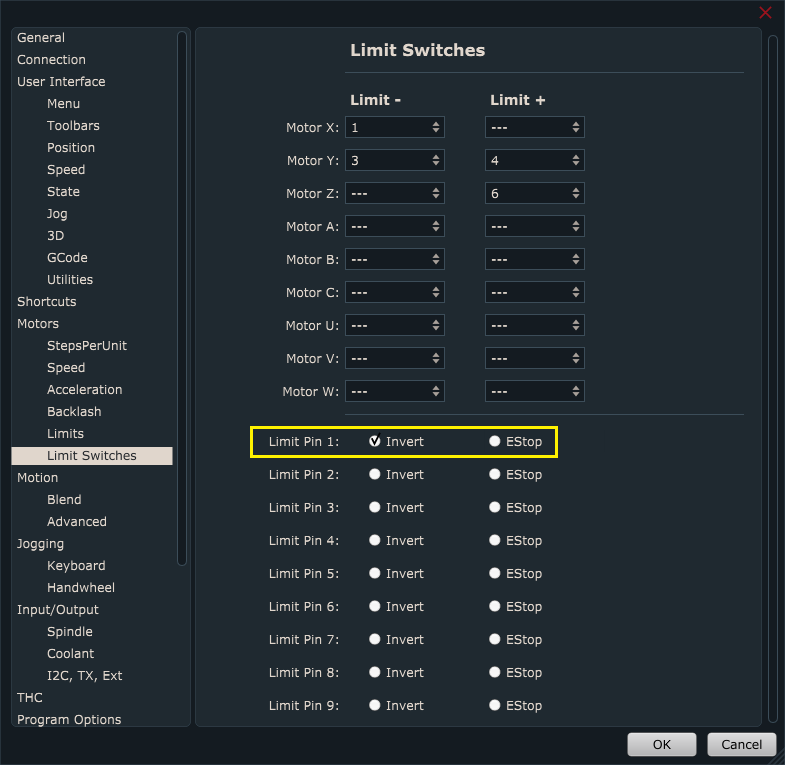
In PlanetCNC TNG under File/Settings/Program Options/Probe & Measure configure input pin that you intend to use for fixed tool sensor.
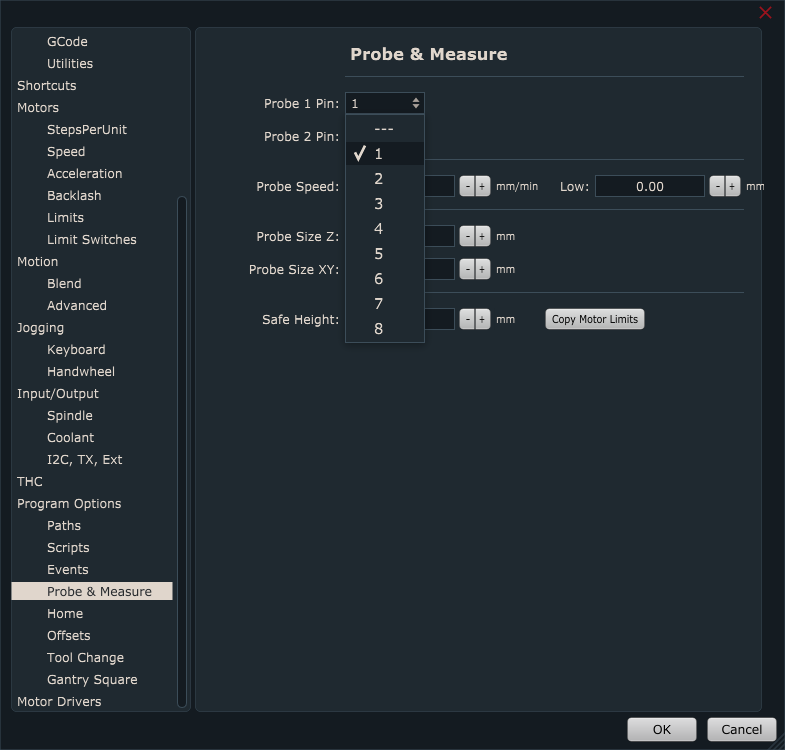
You can select between either Probe 1 or Probe 2 option. It doesn’t matter which one you choose.
Sensor input pin is selected from drop down menu:
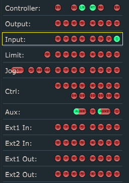
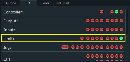
Now that your sensor is connected and configured, it is best to activate sensor by hand to check if everything is functioning OK. Jog your machine (it can be in any direction) and see if machine stops when you activate sensor.
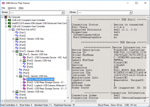
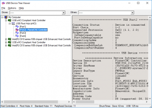
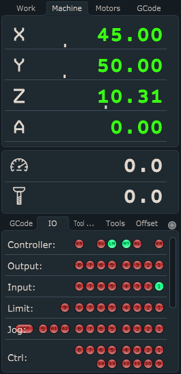
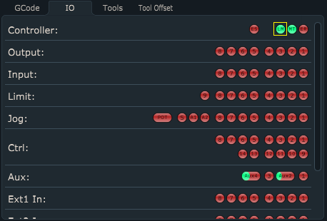
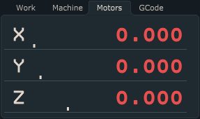
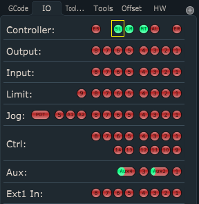
Under IO tab of main display check if input is activated correctly:
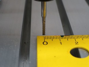
Now move machine to position where fixed sensor is mounted. Make sure that tool is right above the center of fixed tool sensor or in case that you use micro switch, above the lever.
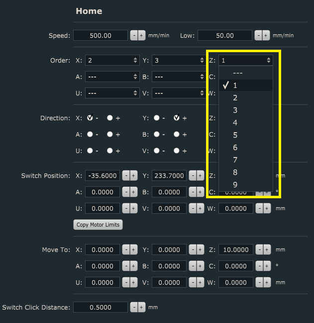
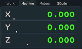
Write down Machine coordinates of X and Y axis. These values will be used for configuration of sensors X and Y axis position:
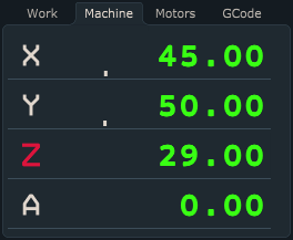
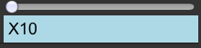
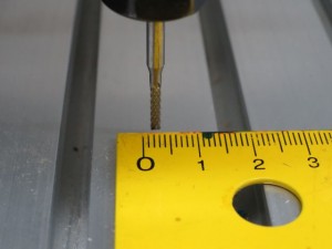
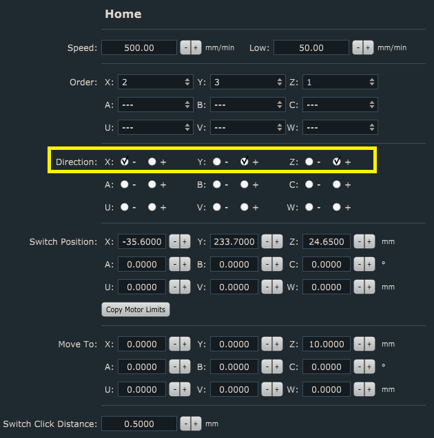
Jog Z axis towards the sensor. When sensor is activated, write down Machine coordinate of Z axis. This value will be used for configuration of sensor Z axis position:
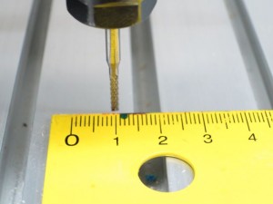
We would like to emphasize that it is very important what kind of tool is used when obtaining Z axis position value, because all future tool measurements will be dependent on this value. That is why we call this tool also a default tool. Default tool should not be too long or too short. It should be some normal length.
Signs that your default tool was not suitable are usually Z axis plunging into machine table or Z axis activating limit switch after tool offset measurement.
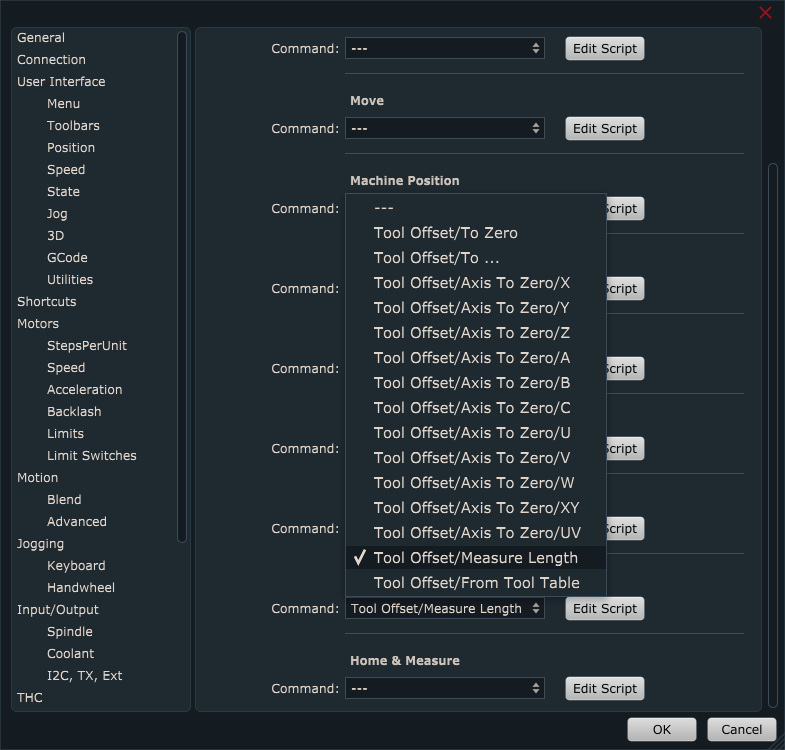
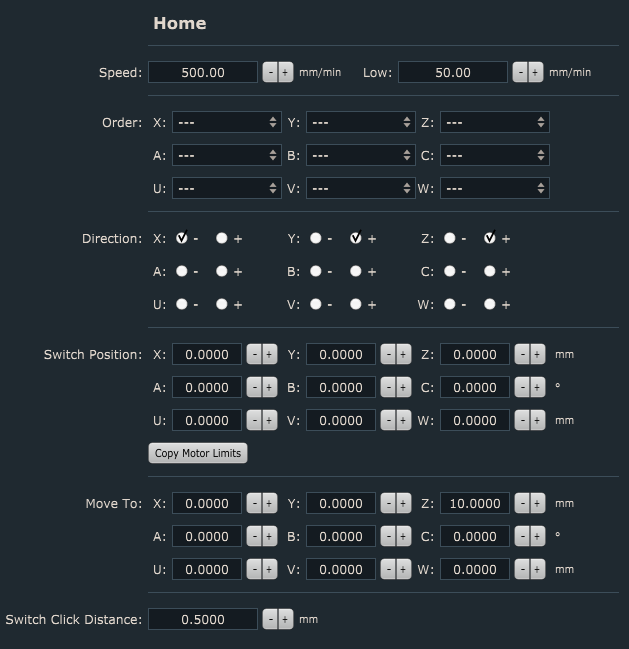
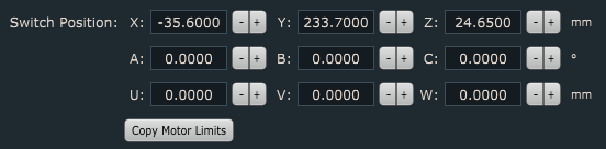
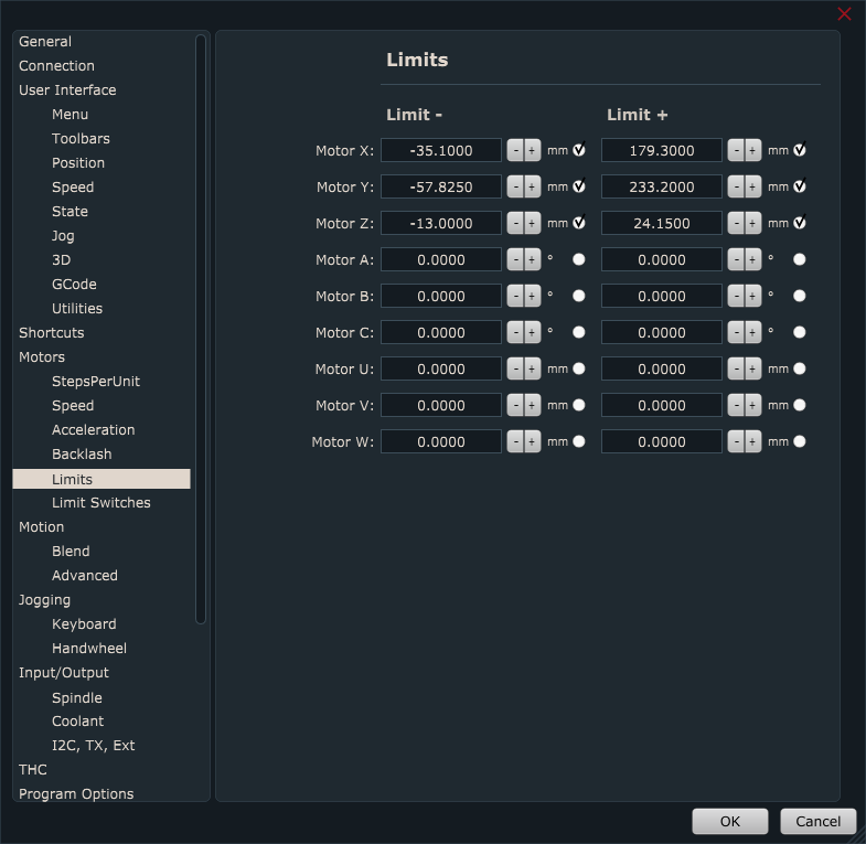
Under File/Settings/Program Options/Offsets/Tool Offset/Measure Length, insert values that you previously wrote down for Sensor Position X,Y and Z:

Speed & Low:
Speed and Low are speed values of first and second tool offset measurement moves (only Z axis).
First reference move will be performed at Speed value. After fixed tool sensor is activated, machine retracts for switch click distance and starts with the second measurement move, but this time at Low speed value. Make sure that Speed value is not set too high to the point where fixed tool sensor, tool or machine could get damaged. Low value should be significantly lower that Speed value.
Safe Height: After both tool offset measurement moves are finished, machine will ascend to Safe Height value and return to previous position.
Switch Click Distance: This is the distance from the point where fixed tool sensor is activated and to the point when it is deactivated.
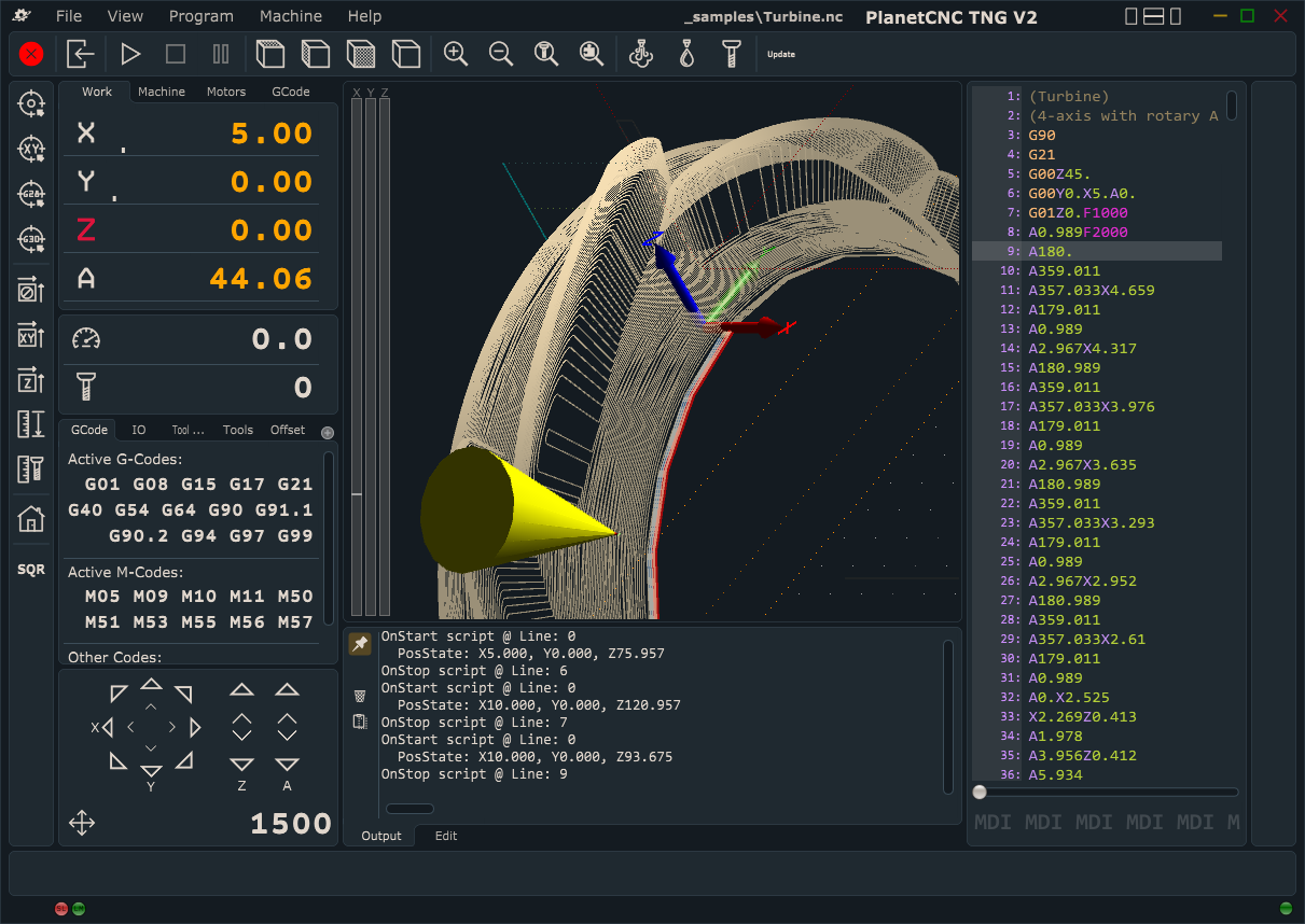
Measuring tool offset with PlanetCNC TNG software
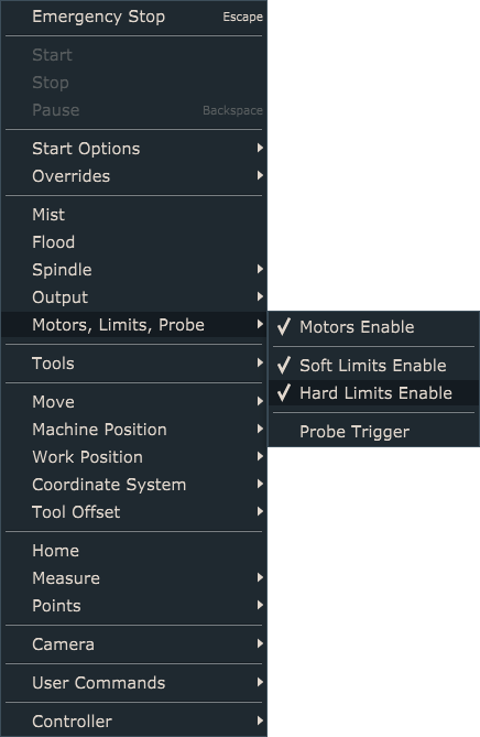
Tool offset measure procedure can be executed via menu item Machine/Tool Offset/Measure Length or with left toolbar button:

Default sequence of Tool Offset Measure procedure:
-Machine will ascend to safe height at current machine position and move to fixed sensors XY position.
-Machine will descend towards fixed tool sensor with Speed value and when sensor gets activated, Z axis will retract for Switch Click Distance and measure tool offset again at Low speed value. Machine will stop and ascend to safe height.
-Software will set new tool offset value
-Machine will return back to XYZ position
Measure tool offset script file
If you would like to edit script code or have more in-depth look at the procedure itself, you can do that by opening script file.
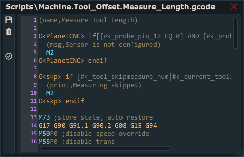
You can access and edit script file in settings under File/Settings/Program Options/Scripts/Tool Offset/Measure Length and click button Edit Script.
Script file will open in TNG gcode editor. In order that Measure Length script file is generated and saved in your profiles Script folder, you need to click Save button.


 .
.