Using “Warp” with PlanetCNC TNG software
This tutorial will explain how to correctly use Machine/Measure/Surface feature and Warp feature using PlanetCNC TNG software and PlanetCNC motion controller.
Since PCB milling is a very delicate and precise procedure (distance between two pads can be only few mils), already smallest PCB surface height irregularities can create bad results.
It is very important that depth of milling is constant over the whole PCB surface throughout the whole milling process. We can achieve this by using “Warp” procedure.
‘Warp’ feature helps apply generated toolpath over bended, curved or uneven surfaces.
The most important step of ‘Warp’ procedure is obtaining surface points. We can either capture each point single-handedly or we can use “Measure Surface” procedure. We recommend the latter.
Points are obtained using probe (or normal engraving tool) which would activate dedicated input of controller.
Step 1:
First you need to configure probe input of controller and probe parameters.
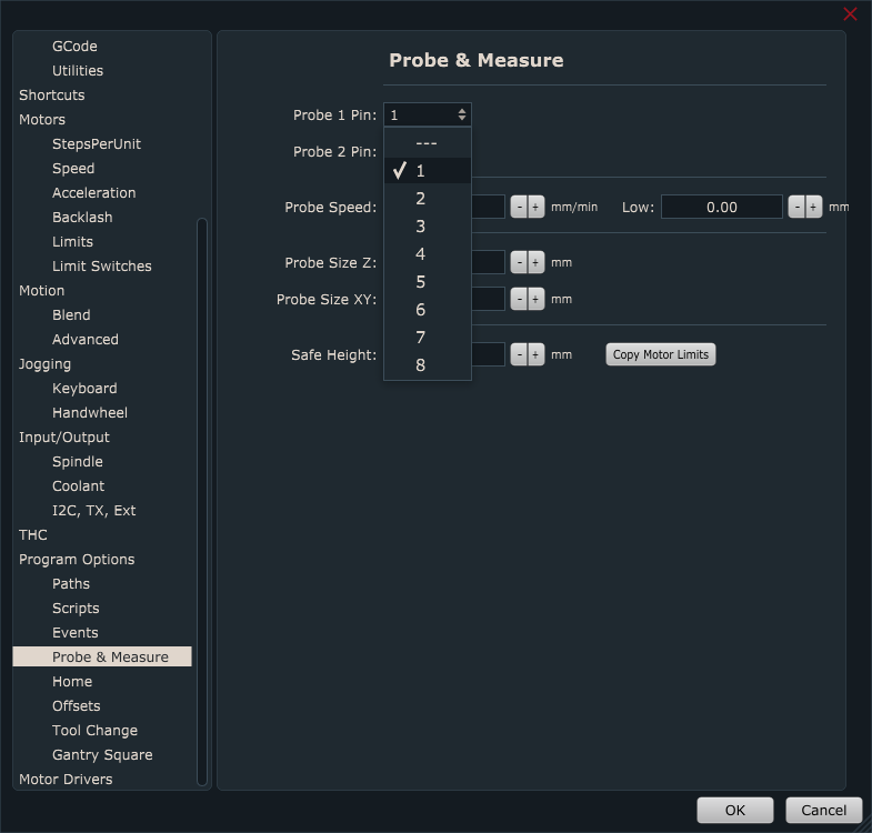
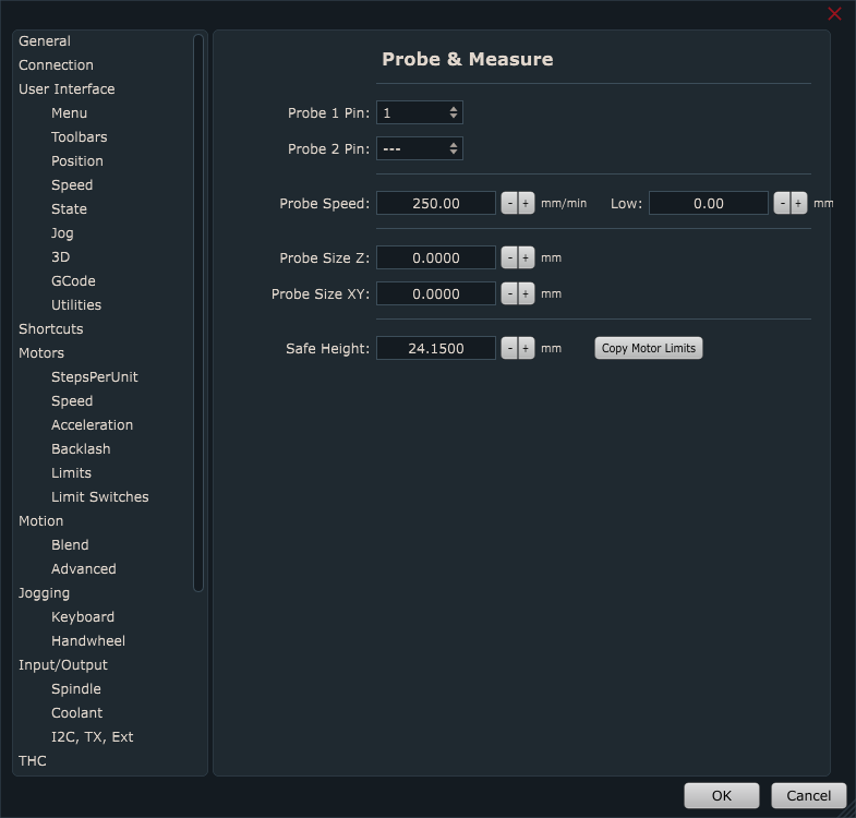
In PlanetCNC TNG under File/Settings/Program Options/Probe & Measure configure input pin of controller that you intend to use surface point measuring.
You can select between either Probe 1 or Probe 2 option. It doesn’t matter which one you choose.
Probe speed will define at which speed machine Z axis will descend to obtain single surface point. It is recommended that you choose suitable value for your machine capabilities. Many times Z axis motor is not capable of higher values of speed and accelerations since it cannot sustain the inertia. In such cases, usually Z axis motor will loose steps, and measurement will be faulty.
Low: After initial first probe activation, machine will repeat measurement again, but this time at Low speed.
Probe Size Z: Length of probe. If you will measure same copper board that will later be used for PCB engraving set this value at 0.
Probe Size XY: Radius of the stylus ball of touching probe.
Safe Height: Height value to which machine ascends in-between measurement procedure.
Step 2:
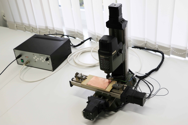
Place your workpiece material (in future text ‘copper board’) to machines table. Mount it properly, so that you avoid any inconveniences later such as vibration, dislocation etc…also make sure that copper board is not in contact with the machine table.
Step 3:
Since copper board itself is conductive material, it can already be used as sensor. You can solder wire to it or you could just use mounting screw to attach connection wire to copper board.
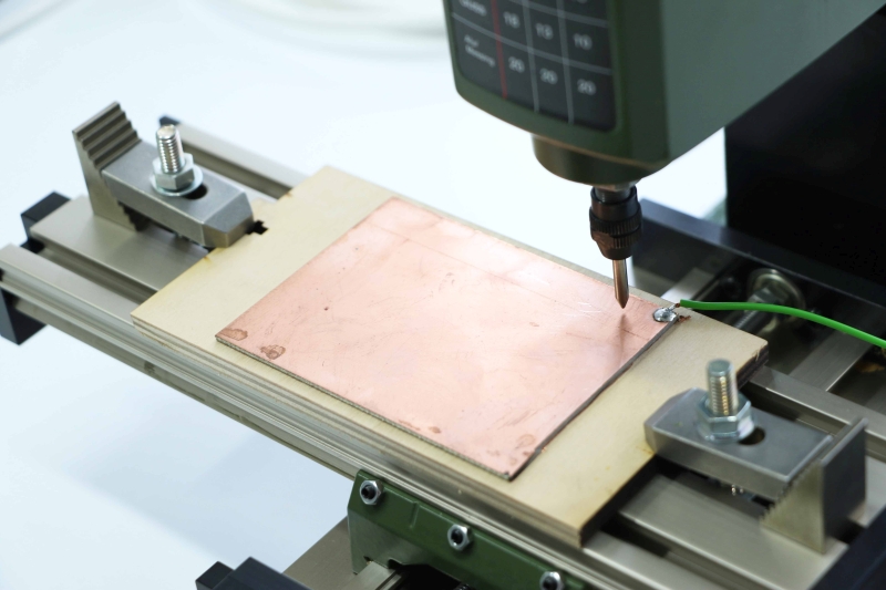
Now connect wire from your copper board to controllers ‘sensor’ input.
Other wire should be connected to controllers GND terminal. Other end of this wire can be clamped to engraving tool:
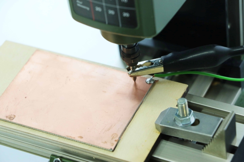
While Mk3/4 controller has a designated sensor input, Mk3 controller uses assignable inputs, so you can connect copper board wire at any input of Input header and configure it in settings later.
Step 4:
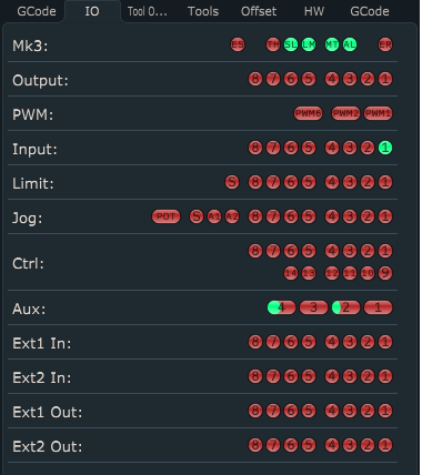
Now open IO tab and check if correct input is activated under “Input” panel. This is just to be sure that everything is working correctly. Image below shows that Input 1 is activated.
Step 5:
Jog your machine to desired initial origin point of your copper board, usually its corner, and click: “Machine/Work Position/Axis to Zero/XY” or click “Work Position Axis to Zero XY” button from toolbar.
With work position XY set to zero, you have initial point of your workpiece material from which you will start your ‘Warp’ measuring as also later align your g-code program.
Step 6:
Now that we set zero XY work positions, we can start with surface point measuring.
Click “Machine/Measure/Measure Surface”:
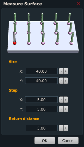
“Measure surface” user dialogue will appear:
Size X: X axis dimension of measuring area surface.
Size Y: Y axis dimension of measuring area surface.
Step: Distance between two neighborly measuring points
Return Distance: After probe touches the surface it will retract for this distance.
Step 7:
After you click OK, machine will begin measuring surface points of copper board.
Step 8:
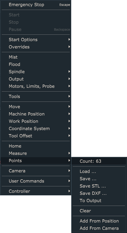
When surface measuring procedure is finished, measured points will be present under Machine/Points. User can save this group of settings as a file.
Step 10:
Now open your Gerber file using “File/Import Gerber”:
Step 11:
To apply “Warp” click: “Program/Warp” and click “From Points…” button.
Table will be populated with coordinates of measured points:
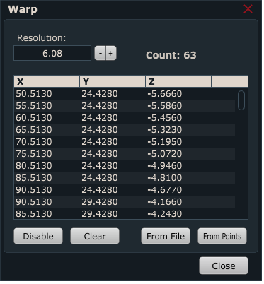
Click Close.
Step 13:
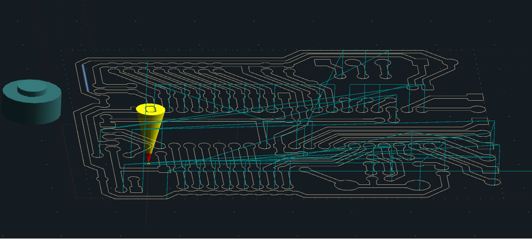
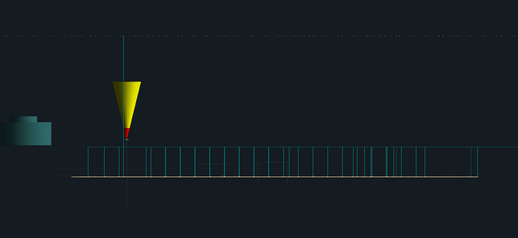
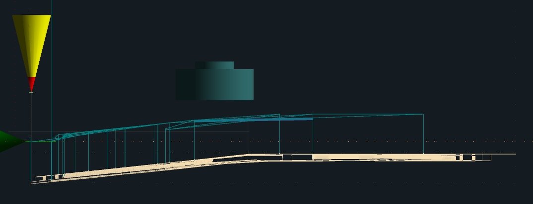
You will notice that the displayed toolpath has changed in order to compensate for boards curved surface. This is much more evident if you set parameter “Alpha” in settings(File/Settings/User Interface/Colors/Alpha).
These are all steps required to apply Warp with your program. Machine will mill at constant depth no matter of the surface curvature.
PLEASE NOTE:
“Measure surface” script file is available for edit.
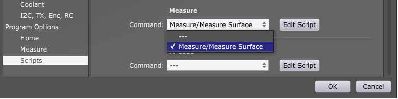
You can open and edit script file if you click: “File/Settings/Program Options/Scripts/Measure” and select “Measure/Measure Surface” from drop down menu. Click: “Edit Script” and script file will open in your default text editor.
Alternatively you can open surface measure script file “Machine.Measure.Measure_Surface.gcode” located in “PlanetCNC64.Scripts” folder with your text editor.