Serial communication(MODBUS relay board) with PlanetCNC TNG – Part 3
In this part, we will use and configure Expr.txt file so that we will be able to control relay board via serial communication using Modbus protocol. Expression array and serial functions described in first two parts will be used in order to achieve this.
Modbus supports communication to and from multiple devices connected to the same wire of serial communication line.
In this tutorial we will use MODBUS RTU frame format.
Modbus “frame” consists of an Application Data Unit (ADU), which encapsulates a Protocol Data Unit (PDU):
ADU = Address + PDU + Error check
PDU = Function code + Data
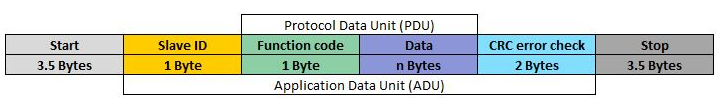
If we put the table above in context, with TNG we will send suitable ADU frame to our slave device(relay board) in order that we will successfully control it.
By using array and serial expression functions, we will manipulate data in such way, that each byte will be at correct value and position of transmitted data.
We will use boards user manual for reference regarding the suitable data.
For more about the Modbus protocol you can read on its official site:
https://www.modbus.org/docs/Modbus_Application_Protocol_V1_1b3.pdf
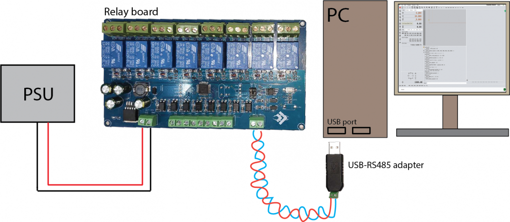
Hardware used
As mentioned earlier, we will use Modbus RTU frame format, which by definition uses RS-485 electrical interface – differential signalling over twisted pair wire.
Relay board uses RS-485 communication interface and by that we need to make sure that differential line is terminated using termination resistor. In our case this is done by placing a jumper in proper position(on board). If multiple boards are used in daisy chain fashion, only last board needs to terminate the differential line. By doing this we prevent signal reflection and therefore data corruption.
This board will be our Modbus slave device.
As a master device, we will use PlanetCNC TNG software, which will send and receive data trough a PC’s COM port. My PC does not have COM port, let alone a RS-485 interface. This is why I will use USB to RS-485 converter. Such device is classified as a USB CDC(communication device class) device and emulates COM port of my computer.
Under Device Manager we can check COM ports ID as “COM11”:
![]()
RS-485 converter and relay board are connected using twisted pair wire.
Identifying relay board
Since this board uses Modbus protocol on top of serial communication(UART), we need to obtain board’s serial communication parameters.
Namely, we need boards address ID and baudrate value. Address ID is in domain of Modbus and it is an important piece of information, since it defines which slave device will respond to our transmitted data. In most cases, Modbus devices use DIP switches for address ID configuration or have some other means for configuring. This relay board does not use DIP switches and we will need to identify the device with different approach.
For start, we need some information about COM port that we intend to use. Specifically, COM ports name, which is important parameter of the serial_open() command..
Type into the MDI:
=serial_list()
Output window will print the returned information:
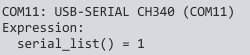
COM ports name is “COM11”.
Using serial_open() command, we can check if this port is ready for transmission of data. We will use the most common serial port parameter setting: 9600–8-N-1 (9600 bits per second, eight (8) data bits, no (N) parity bit, and one (1) stop bit)
=serial_open("COM11",9600,8,0,1,0)
;baudrate at 9600
;8 data bits
;1 stop bits
;none parity
;no flowcontrol
Output window will print the returned information. Remember, this function’s return value gives 0, when port is successfully opened.
![]()
Great, now that this is settled, we can close it and we can prepare the data which will be sent to the relay board in order that we obtain board’s address ID.
Request message and response message data for reading address ID of relay board(as per user manual):
Request message HEX: 0x00 0x03 0x00 0x00 0x00 0x01 0x85 0xDB
  First byte [0x00] is slave device address ID. But since we have no way of knowing it(board does not use DIP switches), we can use reserved value of "00".
    This means that all devices(or only one) on the bus will receive and acknowledge this data and give suitable response.

  Second byte [0x03] is function code
    Function code in Modbus is a specific code used in a Modbus PDU to tell the Modbus slave device what type of memory (i.e. holding registers, input coils, etc)
    to access and what action to perform on that memory (i.e. reading or writing). This PDU uses function code 3, which is used for reading holding registers.
    Holding registers are the most universal 16-bit register, may be read or written, and may be used for a variety of things including inputs, outputs, configuration data, or any requirement for "holding" data.

  Bytes 3 to 6 [0x00 0x00 0x00 0x01] are starting register address and the number of registers we want to read.

  Last two bytes [0x85 0xDB] are CRC 16-bit calculated value. CRC 16-bit value is first calculated and then appended to the end position of array.

Response message HEX: Expected return data should be 0x00, 0x03, 0x02, 0x00, 0x01, 0x44, 0x44.
5th byte of the return data is boards address ID -> HEX: 0x01 ; DEC: 1
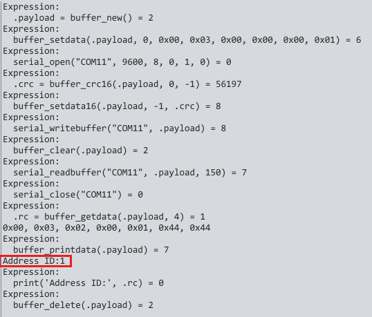
Whole code for reading board’s address ID:
=.payload = array_new()
array_setdata(.payload, 0, 0x00, 0x03, 0x00, 0x00, 0x00, 0x01)
serial_open("COM11", 9600, 8, 0, 1, 0)
.crc = array_crc16(.payload, 0, -1)
array_setdata16(.payload, -1, .crc)
serial_writearray("COM11", .payload)
array_clear(.payload)
serial_readarray("COM11", .payload, 150)
serial_close("COM11")
.rc = array_getdata(.payload, 4)
print('Address ID:', .rc)
array_delete(.payload)
Description of used functions:
=.payload = array_new()  -> new array with handle .payload is created
array_setdata(.payload, 0, 0x00, 0x03, 0x00, 0x00, 0x00, 0x01) -> we set data to .payload array
serial_open("COM11", 9600, 8, 0, 1, 0) -> opens COM port and sets parameters
.crc = array_crc16(.payload, 0, -1) -> calculates CRC 16-bit value of .payload array data
array_setdata16(.payload, -1, .crc) -> we append 16-bit CRC data at the end position of .payload array
serial_writearray("COM11", .payload) -> sends .payload array data via COM11 port
array_clear(.payload) -> we clear .payload array data
serial_readarray("COM11", .payload, 150) -> we read the response data from relay board and set it to .payload array
serial_close("COM11") -> closes COM11 port
.rc = array_getdata(.payload, 4) -> we set the 5th byte (zero type numbering is used) of received data into .rc variable
print('Address ID:', .rc) -> prints .rc value
array_delete(.payload) -> deletes .payload array handle
Relay On/Off control
Now that we know board address ID, and since this is a relay board, lets control one of the relays on/off.
Request message and response message data for relay No. 1 ON(as per user manual):
Request message HEX: 0x01 0x05 0x00 0x00 0xFF 0x00 CRC-byte CRC-byte
  First byte [0x01] is slave device address ID. As we know, address ID of relay board is 1.

  Second byte [0x05] is function code. Function code in Modbus is a specific code used in a Modbus PDU to tell the Modbus slave device what type of memory (i.e. holding registers, input coils, etc) to access
    and what action to perform on that memory (i.e. reading or writing). This PDU uses function code 5, which is used to write a single output to either ON or OFF in a remote device.

  Bytes 3 to 6 [0x00 0x00 0xFF 0x00] are coil address(first relay at 0...) and the constant value for ON 0xFF 0x00, and a constant value for OFF 0x00 0x00.

  Last two bytes are CRC 16-bit calculated value. These two bytes are not set together with first six bytes. CRC 16-bit value is first calculated and then appended to the end position of array.
Whole code for turning relay 1 ON:
=.payload = array_new()
array_setdata(.payload, 0, 0x01, 0x05, 0x00, 0x00, 0xFF, 0x00)
serial_open("COM11", 9600, 8, 0, 1, 0)
.crc = array_crc16(.payload, 0, -1)
array_setdata16(.payload, -1, .crc)
serial_writearray("COM11", .payload)
array_clear(.payload)
serial_readarray("COM11", .payload, 150)
serial_close("COM11")
.rc = array_getdata(.payload, 4)
array_printdata(.payload)
print('Address ID:', .rc)
array_delete(.payload)
Whole code for turning relay 1 OFF:
=.payload = array_new()
array_setdata(.payload, 0, 0x01, 0x05, 0x00, 0x00, 0x00, 0x00)
serial_open("COM11", 9600, 8, 0, 1, 0)
.crc = array_crc16(.payload, 0, -1)
array_setdata16(.payload, -1, .crc)
serial_writearray("COM11", .payload)
array_clear(.payload)
serial_readarray("COM11", .payload, 150)
serial_close("COM11")
.rc = array_getdata(.payload, 4)
array_printdata(.payload) print('Address ID:', .rc)
array_delete(.payload)
Implementing Modbus communication within TNG software
Executing these commands from MDI is nice for testing, but not really practical in real application. Best way to implement MODBUS communication within the TNG would be to write an expression function which would inhibit all necessary code for master modbus <-> slave communication.
To read more about Expr file and its properties, you can follow link below:
CNC machine semaphore application using Expressions (Expr.txt)
Create new expr file and name it e.g. Expr_MB_relay.txt. We can include two expression functions in this file, one for relay ON and other for relay OFF.
Lets name them #RelayControl_ON and #RelayControl_OFF. Include the corresponding code for each function.
The code of Expr_MB_relay.txt file would look like this:
#RelayControl_ON
.payload = array_new();
array_setdata(.payload, 0, 0x01, 0x05, 0x00, 0x00, 0xFF, 0x00);
serial_open("COM11", 9600, 8, 0, 1, 0);
.crc = array_crc16(.payload, 0, -1);
array_setdata16(.payload, -1, .crc);
serial_writearray("COM11", .payload);
array_clear(.payload);
serial_readarray("COM11", .payload, 150);
serial_close("COM11");
.rc = array_getdata(.payload, 4);
array_printdata(.payload);
print('Address ID:', .rc);
array_delete(.payload);

#RelayControl_OFF
.payload = array_new();
array_setdata(.payload, 0, 0x01, 0x05, 0x00, 0x00, 0x00, 0x00);
serial_open("COM11", 9600, 8, 0, 1, 0);
.crc = array_crc16(.payload, 0, -1);
array_setdata16(.payload, -1, .crc);
array_writearray("COM11", .payload);
array_clear(.payload);
serial_readarray("COM11", .payload, 150);
serial_close("COM11");
.rc = array_getdata(.payload, 4);
array_printdata(.payload)
print('Address ID:', .rc);
array_delete(.payload);
You can run expression functions either from .NC file, script file, button file, M code file, expression file etc..
Now, if you would like to execute these two functions within a .NC program or gcode script file, you can use (expr, ) comment function:
%
.
.
.
G00 X0 Y20
G01 Z5
(expr,exec("#RelayControl_ON"))
G01 Z-1
G00 Z5
(expr,exec("#RelayControl_OFF"))
.
.
.
%
While both examples of Modbus functions described above would work, it would not be a good example of how such communication should be handled.
For each request data sent, we also need to read the response data. Response is an automated process from slave device, and we can use the response data in order that we can verify that request procedure has been acknowledged, processed and correctly executed. In next part we will describe how to correctly write more reliable expression code for Modbus communication.
Continued at part 4:
https://planet-cnc.com/serial-communication-with-planetcnc-tng-part-4/