Modbus communication with HuanYang VFD and PlanetCNC TNG – Part 1
This tutorial will describe the necessary steps for successful control of your HuanYang VFD(model: HY01D523B) using PlanetCNC TNG software.
Before we start, I would really recommend reading tutorials related to serial communication, MODBUS and PlanetCNC TNG software. These tutorials explain the tools provided by PlanetCNC and how to use them in order to communicate with external equipment using serial communication(MODBUS).
Description of serial communication functions(data preparation):
Serial communication(MODBUS relay board) with PlanetCNC TNG – Part 1
Description of serial communication functions(data send/read):
Serial communication(MODBUS relay board) with PlanetCNC TNG – Part 2
Establishing communication with Modbus device(basic):
Serial communication(MODBUS relay board) with PlanetCNC TNG – Part 3
Establishing communication with Modbus device:(advanced)
Serial communication(MODBUS relay board) with PlanetCNC TNG – Part 4
1. Introduction
HuanYang inverters are very common and popular among hobby CNC machinists. They can be used for different applications, but in a CNC machine context they are normally used to drive the spindle motor of CNC machine.
Through parameter configuration, user can configure inverter behavior in such way, so that it complies with application needs and spindle motor hardware requirements that it is used with.
Such CNC application requirement would be achieving spindle control trough gcode program commands. Meaning, whenever commands such as M3, M4, M5 appear in the gcode program, spindle motor of CNC machine should respond with appropriate action.
Example: M3 S10000 should turn ON the spindle and ramp up spindle to 10000 rpm, M4 should rotate spindle motor in reverse direction and M5 gcode command should stop the spindle.
There are multiple ways to achieve this. User can manually operate inverter from front panel, and press the buttons and rotate the knobs at the right moment – not really useful.
Second would be that inverter control terminal inputs will control the motor behavior. In practice this means that external board will be needed for inverter input control.
Example: User connects relay board with cnc controller and configure cnc software in such way, that controller output pins will respond to gcode commands and activate appropriate relays. Stable spindle speed control can be difficult to achieve due to analog voltage signals and EM interference.
Last and the most elegant way would be to control the inverter using MODBUS communication. No relays, no additional wires, no analog voltage etc..
Example: PlanetCNC software sends appropriate data trough COM port of computer via MODBUS protocol to inverter. MODBUS is by definition used with RS-485 electrical interface, which is very robust and resistant to EM interference.
This part of tutorial will describe how to:
-connect HuanYang inverter with PC using a USB to RS-485 adapter
-key Modbus related inverter parameter configuration
-Expression file manipulation
-Communication test
2. Hardware used
HuanYang inverter:
HuanYang VFD model: HY01D523B
USB to RS-485 converter:
My PC does not have COM port, let alone a RS-485 interface. This is why I will use USB to RS-485 converter. Such device is classified as a USB CDC(communication device class) device and emulates COM port of my computer.
It makes sense to buy or own two pieces of such adapter converter. Many times these cheap units malfunction or do not even work from the start. So I recommend that you make a test with two of these adapters and create a loop, where you can test their functionality.
Such test is described to some extent in Modbus relay board tutorial:
Serial communication(MODBUS relay board) with PlanetCNC TNG – Part 2
PlanetCNC TNG software:
As a master device, we will use PlanetCNC TNG software, which will send and receive data trough a PC’s COM port.
NOTE: Please use latest available version from here: https://planet-cnc.com/software/
3. Inverter parameter configuration
NOTE: Make sure that main power supply and spindle motor are connected as per user manual of inverter. Connection of power supply and spindle motor as also spindle motor related parameters are not subject of this tutorial.
Once inverter is turned ON and you can access the parameter menu, you will need to change some parameters. The following parameters refer to MODBUS communication:
PD001-> set to value 2
Source of run commands: Communication port
PD002-> set to value 2
Source of operating frequency: Communication port
PD163-> set to value 1
Communication address: Device address set to 1
PD164-> set to value 1
Communication Baud Rate: 9600 b/s
PD165 -> set to value 3
Communication data method: 8N1 for RTU. 8 data bits, no parity bit and 1 stop bit.
Use front panel buttons to navigate trough the parameter menu.
4. Connection of USB to RS-485 adapter and inverter
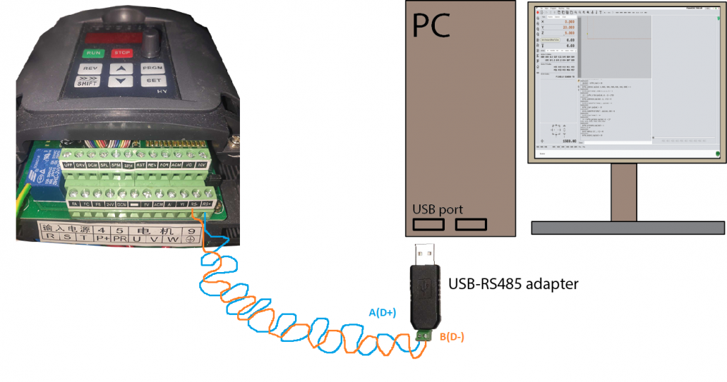
Connect A(D+) terminal of RS-485 adapter with RS+ terminal of inverter, using first wire of the twisted pair.
Connect B(D-) terminal of RS-485 adapter with RS- terminal of inverter, using second wire of the twisted pair.
Connect adapter in one of the PC’s USB slots.
Under Device Manager check COM ports ID. In my case, adapter is recognized as “COM10”:
![]()
This will be important piece of information, when we will edit the Expression file which is responsible for serial communication.
5. Expression and Gcode script files
For proper functionality user needs to place additional files to its TNG profile folder.
Four expression files should be placed in the root profile folder, and three gcode script files should be placed in Scripts folder.
To download file(s), click right mouse button and select Save Link as…
Expression files:
Expr_VFD_beta.txt -> download
Expr_Modbus_HuanYang_VFD_control_speed.txt -> download
Expr_Modbus_HuanYang_VFD_control.txt -> download
Expr_Modbus_HuanYang_VFD_Parameter_Read.txt -> download
Gcode script files:
M3.gcode -> download
M4.gcode -> download
M5.gcode -> download
File locations:
Expr_VFD_beta.txt                           -> file should be placed/pasted in the root folder of user profile folder
Expr_Modbus_HuanYang_VFD_Parameter_Read.txt -> file should be placed/pasted in the root folder of user profile folder
Expr_Modbus_HuangYang_VFD_control_speed.txt -> file should be placed/pasted in the root folder of user profile folder
Expr_Modbus_HuangYang_VFD_control.txt       -> file should be placed/pasted in the root folder of user profile folder

M3.gcode -> file should be placed/pasted in the Scripts folder
M4.gcode -> file should be placed/pasted in the Scripts folder
M5.gcode -> file should be placed/pasted in the Scripts folder
6. Expression file configuration
Open Expr_Modbus_HuanYang_VFD_Parameter_Read.txt file in your text editor, and at #OnInit section of the file check if variables below, correspond with parameters of inverter.
port = "COM10"  -> should match to the ID of your USB to RS-485 adapter under Device Manager/Ports(COM & LPT)
baudrate = 9600 -> should correspond to the value of inverter parameter PD164 ; in my case, inverter parameter value PD164 is set to 1 (baudrate 9600)
bits = 8        -> should correspond to the inverter parameter PD165 ; in my case, inverter parameter value PD165 is set to 3 (8N1 for RTU, 8 data bits, no parity bit, 1 stop bit)
parity = 0      -> should correspond to the inverter parameter PD165 ; in my case, inverter parameter value PD165 is set to 3 (8N1 for RTU, 8 data bits, no parity bit, 1 stop bit)
stopbits = 1    -> should correspond to the inverter parameter PD165 ; in my case, inverter parameter value PD165 is set to 3 (8N1 for RTU, 8 data bits, no parity bit, 1 stop bit)
addr = 1        -> should correspond to the inverter parameter PD163 ; in my case, inverter parameter PD163 value is set to 1 (device address 1)
Same should be done with Expr_Modbus_HuangYang_VFD_control.txt file.
7. Communication test
Open TNG software, and under View/Panel make sure that Utilities option is enabled.

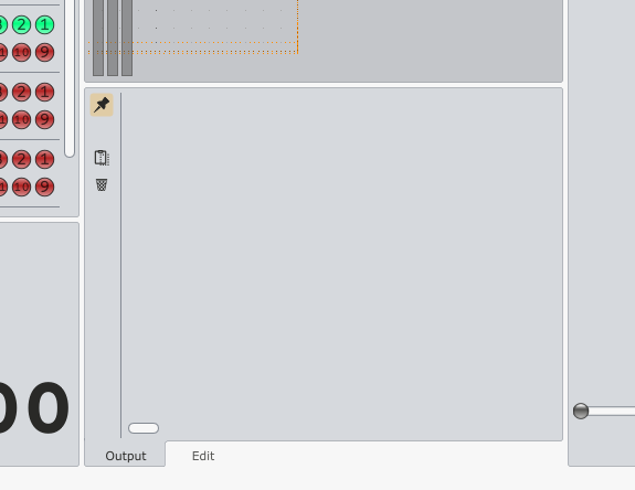
Output window should be displayed at the bottom middle section:
-Check if USB to RS-485 adapter is connected with PC
-Check if USB to RS-485 adapter is recognized under Control Panel/Device Manager
-Check if connection with twisted pair between inverter and adapter is correct
-Check if inverter is turned ON
-Check if Modbus related inverter parameters are correct
-Check if Expression and gcode file locations are correct
-Check if COM name of adapter matches the name variable in Expression files under #OnInit section.
-Check if serial communication parameter values in Expression files under #OnInit section matches inverter parameter values
In the MDI window type following text:
=exec('#Modbus_HuanYang_VFD_Parameter_read')

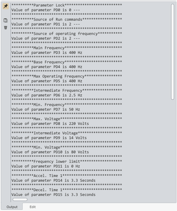
This will start an expression function which will print inverter communication and motor related parameters into the output window as also create a .txt file in main user profile. So, after hitting Enter, with any luck, you should se this in the output window:
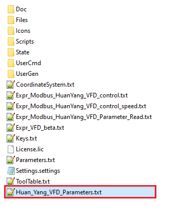
As also newly created file in your root profile folder:
8. Troubleshooting
If it takes long period of time for procedure to finish and nothing is printed into the output window, it indicates that something is not ok.
Type into the MDI window the following text:
=debug = 1
Now run the procedure again:
=exec('#Modbus_HuanYang_VFD_Parameter_read')
Observe the output window and the printed text.
If any COM port related problem exists, such as adapter is not connected, or COM name does not match the one in #OnInit section of expression files, this will be displayed :

If the response from script will display “response check failed with error code: -1”, this means that the returned data from inverter is not as per specification of this modbus expression function.
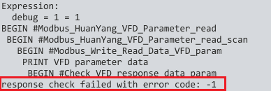
In such case, it makes sense to investigate more in detail, and see what exactly is returned from the inverter.
In the file Expr_Modbus_HuanYang_VFD_Parameter_Read.txt, edit line 109, and uncomment it(remove the ; symbol):


Save file, and restart TNG, or just open settings and confirm them. This will reload the modified expression file.
When the procedure is executed again, returned data will also be printed:

If printed values do not make sense or there is no printed data, we can dig deeper and search for a reason of this issues somewhere else, maybe faulty adapter or inverter is not configured correctly/has unresponsive terminal.
Next part will describe spindle control: Part 2
