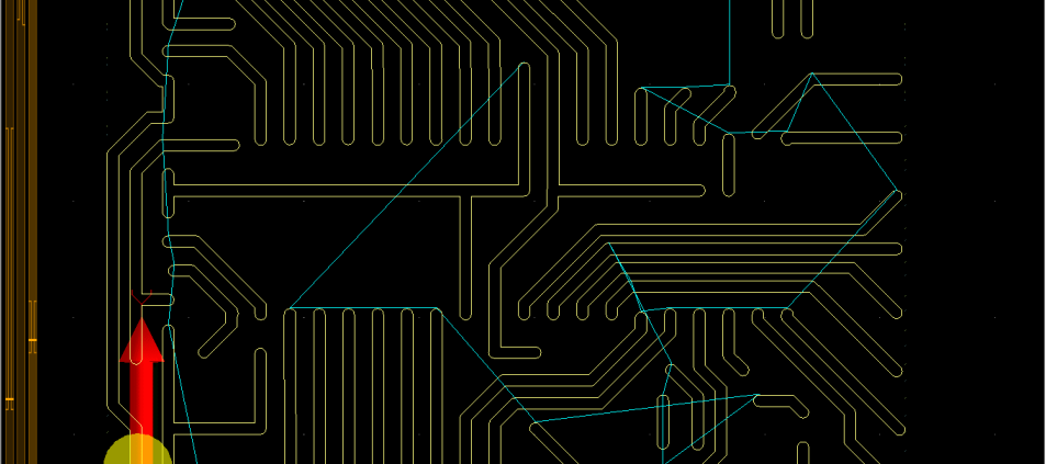
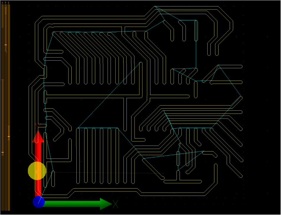
How to mill and drill PCBs from Gerber and NC Drill files?
MILLING PCB’S WITH CNC USB CONTROLLERS
This tutorial is intended to help you with production of one-sided PCBs with your CNC machine.
Before any work is done with machine you must be sure that the ‘Gerber’ files you intend to import in CNC USB controller software are correct and are generated with correct parameters.
Some Gerber files have all parameter configuration already written in the comment section at the beginning of the file.
You could however figure it out from the format of the coordinates but this is not exactly trivial (trial and error) thing to do.
The steps for milling a PCB are as follows:
1.) Mounting copper board to machine table
2.) Set “Current XY” offset
3.) Measuring the surface of the board (“Warp”)
4.) Import “NC drill” file
5.) Drill holes
6.) Import “Gerber” file
7.) Apply “Warp”
8.) Mill PCB
For the purposes of this tutorial we will be using “NC drill” and “Gerber” files of our Mk1 controller.
1.) Mounting copper board to machines table
2.) Set “Current XY” offset
3.) Measuring the surface of the board (“Warp”)
These first three steps are described in “Warp” tutorial.
4.) Import “NC drill” file
You import your drill files if you click: “File/Import NC drill”.
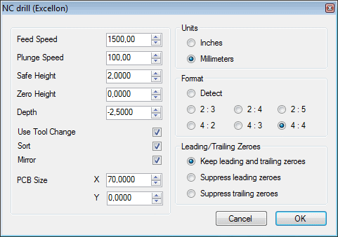
Import dialog will appear, where you can configure the drilling parameters. You will probably leave most of them intact, while others will maybe need some fine tuning.
Description of parameters:
Feed Speed:
‘Feed Speed’ is usually the speed that is used for cutting or milling, and since there will be no cutting involved in the drilling procedure, you can set this value the same as your ‘Traverse Speed’ in settings.
‘Feed speed’ is the speed at which machine will descend from ‘Safe height’ to ‘Zero height’.
Plunge Speed:
‘Plunge speed’ is the speed at which machine will actually drill. Drilling depth will be from ‘Zero height’ to ‘Depth’ height.
Values depend on the RPM of your spindle and the diameter of drilling bit. With higher RPM number you can “afford” greater Plunge Speed values.
Safe Height:
Machine will move up to ‘Safe Height’ in between drilling holes.
If your board is not too curved, then 2mm would be reasonable value.
Zero Height:
Zero height is at PCB’s surface. Machine moves down to this height from ‘Safe Height’ at ‘Feed Speed’.
Value is 0.
Depth:
Holes should be drilled in its entirety, meaning no hole should be drilled half way. So Depth value is basically the thickness of your PCB board with some added safe distance just to be sure that the holes will be drilled “clean”.
For example: 1.6mm + 1mm = 2.6mm
Use Tool Change:
If enabled, g-code program will include tool changes for tools with different diameters. Usually we leave this setting disabled since we drill holes with only one diameter.
You can leave it disabled.
Sort:
Sorts holes to optimize the toolpath to shorten working time.
Mirror:
Mirrors program in XY. If drill path is mirrored you can enable ‘Mirror’ feature in the import dialog, which places toolpath in the right order.
PCB size:
This is approximate size of the PCB and it is important that this value is the same when importing corresponding gerber file.
Units
Specify millimeter or inch units. Software will try to auto-detect correct settings but if imported file looks strange then you should change these values.
Format
Specify number decimal digit format. Software will try to auto-detect correct settings but if imported file looks strange then you should change these values
Leading / Trailing Zeroes
Specify leading and trailing zeroes. Software will try to auto-detect correct settings but if imported file looks strange then you should change these values.
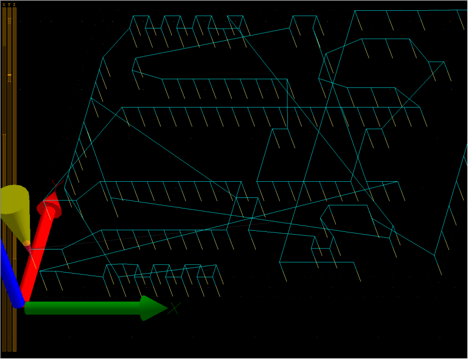
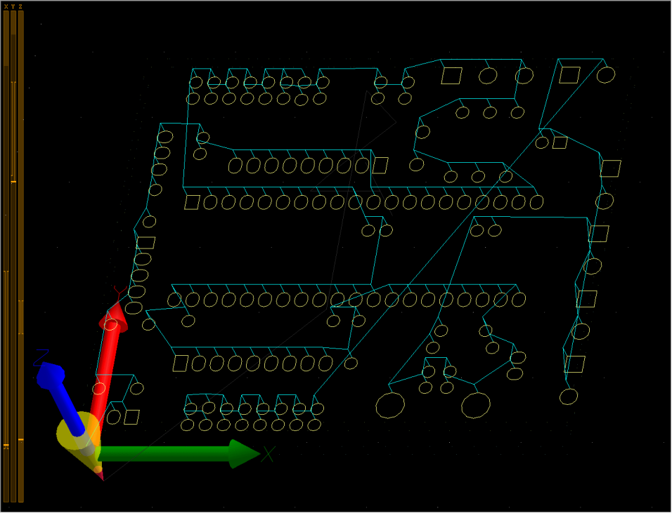
This is how drilling toolpath looks like when import settings configuration is done:
5.) Drill holes
Now that everything is set for drilling holes, you press ‘Start’ button and let the machine do the work.
6.) Import “Gerber” file
To import your “Gerber” files you can click: “File/Import Gerber”. Import dialog will appear where milling parameters can be configured.
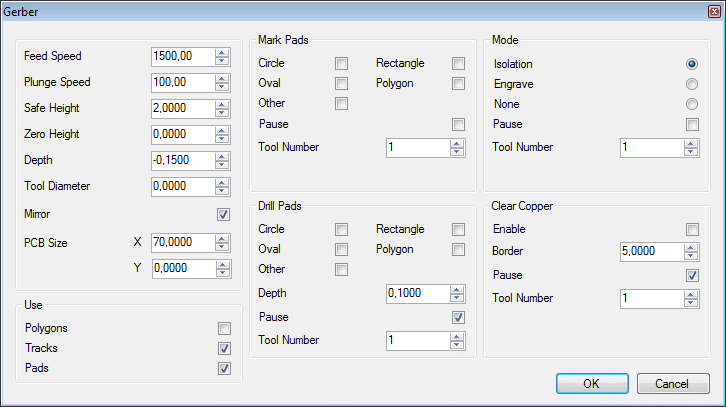
Description of parameters
Feed Speed:
This is the feed rate at which PCB will be milled. It’s probably best for you to “dry” test the various speeds so you make sure machine will not loose steps at certain speeds during the milling process.
Plunge Speed:
‘Plunge speed’ is the speed at which machine descends from ‘Zero Height’ to ‘Depth’ when it starts to mill PCB layout.
Safe Height:
Machine will move up to ‘Safe Height’ in between milling the PCB layout. Also when drilling holes or marking pads.
Zero Height:
This is the the PCB surface. Machine moves down to this height from ‘Safe Height’ at ‘Feed Speed’.
Depth:
Depth of isolation, engraving,marking or drilling holes, depending on the selected option. Machine moves down to this height at ‘Plunge Speed’.
Tool diameter:
Diameter of tool used for milling.
Mirror:
Mirrors program in XY. If PCB layout is mirrored you can enable ‘Mirror’ setting which places toolpath in the right order.
PCB Size: Dimensions of PCB board. This is approximate size of the PCB and it is important that this value is the same when importing corresponding “NC drill” file.
Use
Gerber files can contain different elements such as polygons, tracks and pads.
Polygons:
Use ‘Polygons’ in toolpath calculation.
Tracks:
Use ‘Tracks’ in toolpath calculation.
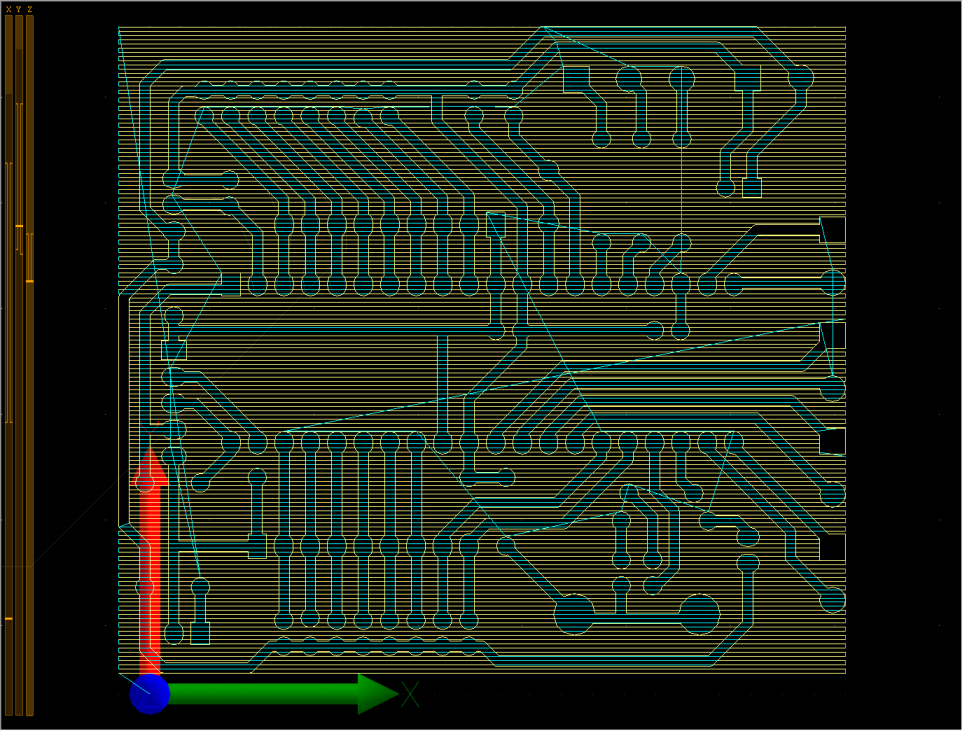
Shape of toolpath when only ‘Tracks’ is used:
Pads:
Use ‘Pads’ in toolpath calculation.
Shape of toolpath when only ‘Pads’ is used:
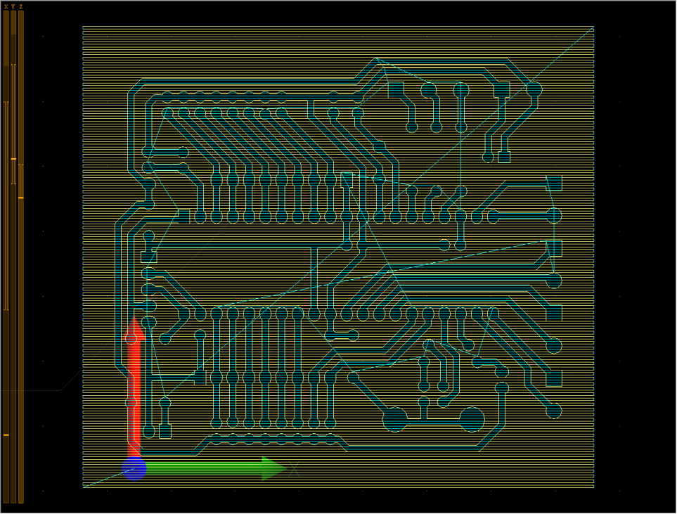
Toolpath when all three options are selected:
Mark Pads: You don’t need to set this, all holes are already drilled.
Drill Pads: You don’t need to set this, all holes are already drilled.
Mode
Toolpath calculation mode.
Isolation:
Enable to mill electrical isolation toolpath.
Shape of toolpath when only ‘Isolation’ is used:

Engrave:
Enable to mill only center line (for example silkscreen or cutout).
Shape of toolpath when only ‘Engrave’ is used:
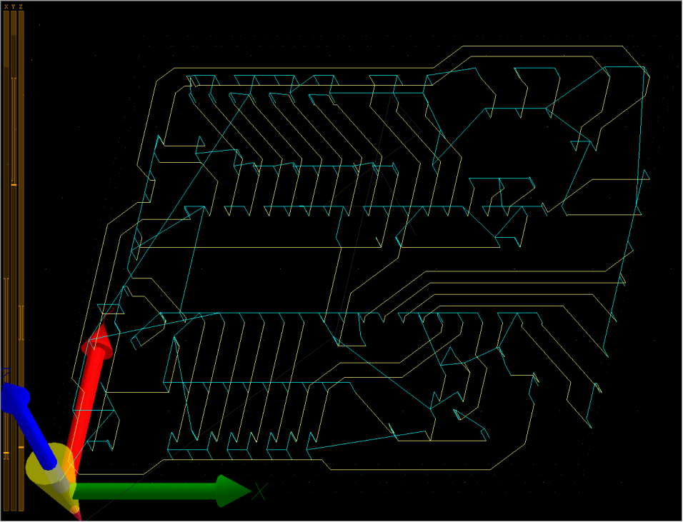
None:
Enable if you want just mark or drill pads.
Pause:
‘Pause’ (M00) G-Code will be inserted at the end of selected toolpath calculation mode.
Tool number:
Number of the tool that will be used for selected toolpath calculation mode.
Usually only ‘Isolation’ option is selected.
Clear copper
Enable:
Enable to generate toolpath that will clear unused copper.
Toolpath with “Clear copper” enabled and with “Boarder” set to 0:
Border:
Distance from PCB outline where copper will still be cleared.
Pause:
Inserts ‘Pause’ (M00) G-Code at the end of clearing copper.
Tool Number:
Number of the tool that will be used for clearing copper.
7.)Apply “Warp
See “Warp” tutorial, Step 9.
