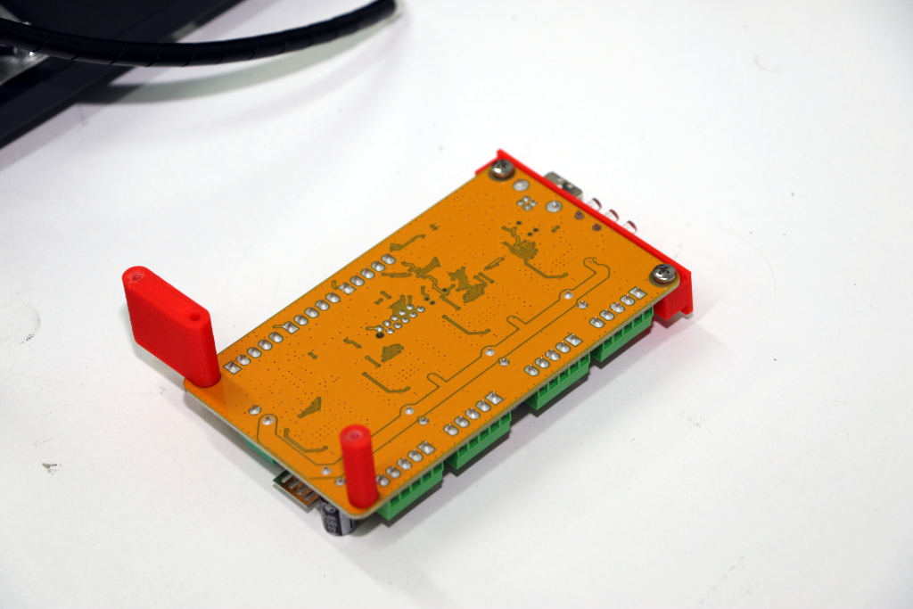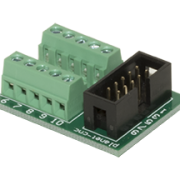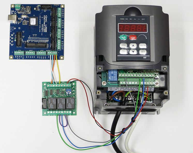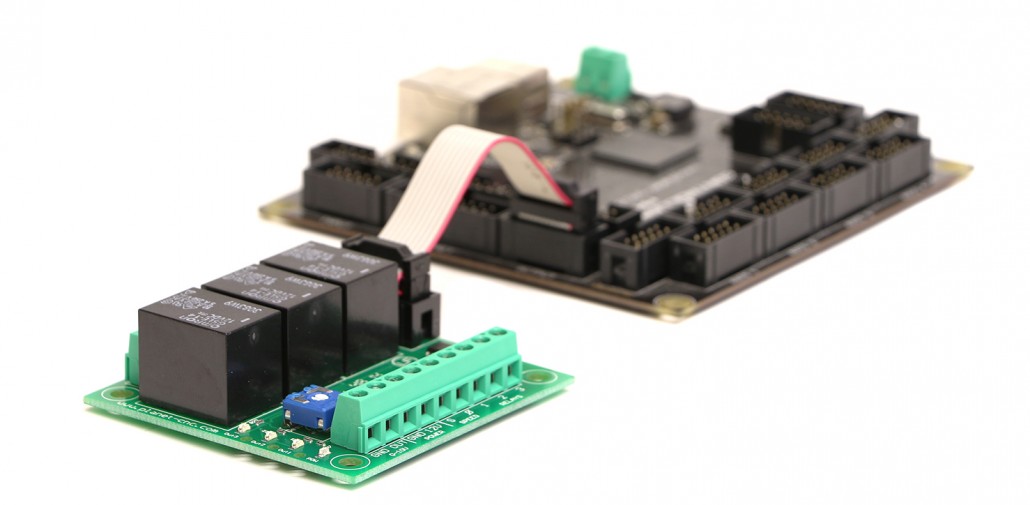
Output board is used for control of external equipment such as VFDs, coolant systems, vacuum pumps etc.
It requires 12V power supply connected to a terminal labeled 12V (be careful with the polarity). Output board has 3 relays and 0-10V output. Relays can be used as NO (normally open) or NC (normally closed).
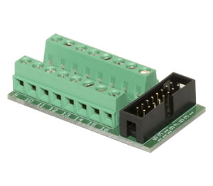
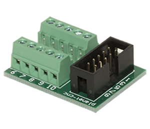
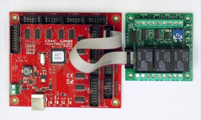
Output board can be connected with controller via 10pin IDC header or screw type terminals labeled “S”, “0”, “1”, “2” and “3”.
1. Output board connector description:
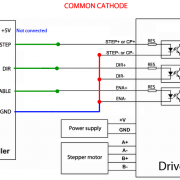
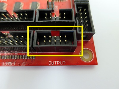
IDC header:
This IDC connector is used to connect output board with controller via 10pin ribbon cable (For Mk2 and Mk3).
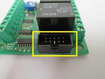
Pin 5 of this connector activates relay 1.
Pin 4 of this connector activates relay 2.
Pin 3 of this connector activates relay 3.
Pin 6 of this connector controls 0-10V output.
Control input terminals:
This screw type connector is used for connection with Mk2/4, Mk3/4 or Mk3DRV controllers(or some other external devices) with output board:
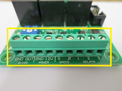
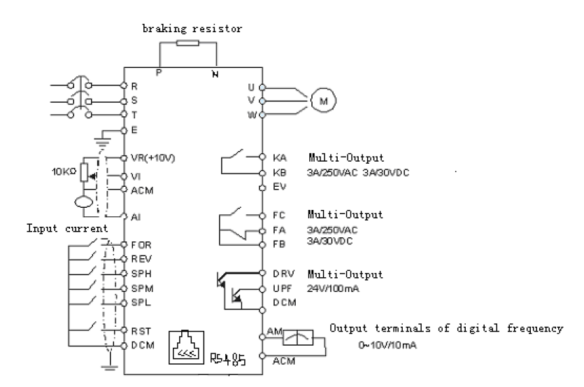
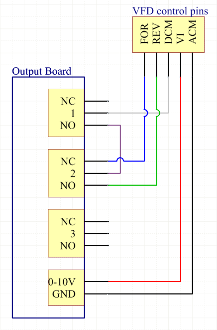
[0-10V; GND, OUT] → to connect variable voltage output with VFD, output
[POWER; GND, 12V] → to connect power supply (12V DC, at least 200mA ), input
[SPEED; S, 0] → to connect varying frequency signal from controller or some other external device, input
S: Frequency signal input from Mk2/4 or Mk3/4 or other external device
0: GND from controller
[RELAYS; 1, 2 , 3] → Control signal input for SPINDLE, MIST or FLOOD from controller (or other external device), input
Input 1 controls relay labelled 1
Input 2 controls relay labelled 2
Input 3 controls relay labelled 3
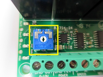
Trimmer:
This trimmer is used for calibrating the 0-10V output:
Relay output terminals:
These are relay connectors. They are used for connection of the controlled device:
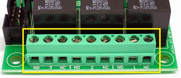
NO- normally open contact of relay
NC- normally closed contact of relay
1 – common movable contact of the first relay
2 – common movable contact of the second relay
3 – common movable contact of the third relay
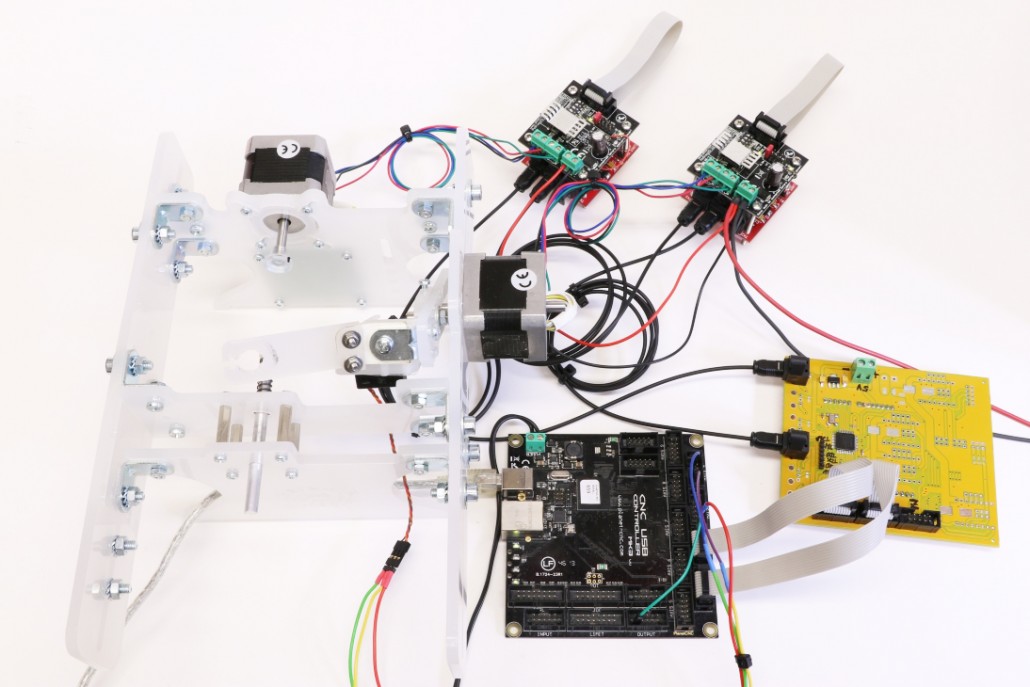
2. Output board and controller connection:
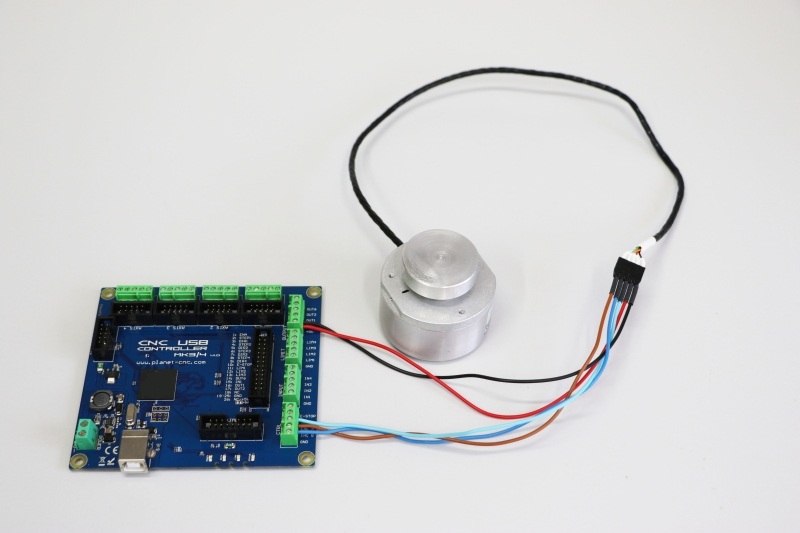
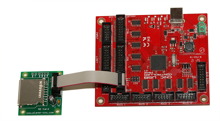
Mk2 and Mk3:
These two controllers use 10pin IDC connector, which makes the connection of controller and output board very easy.
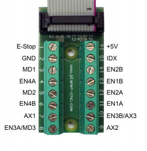
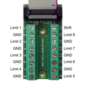
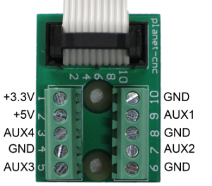
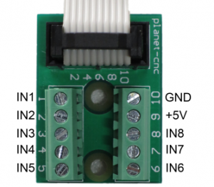
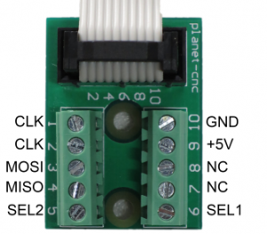
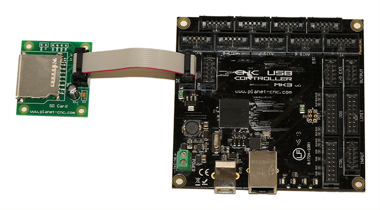
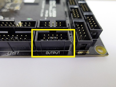
Mk2 output connector:
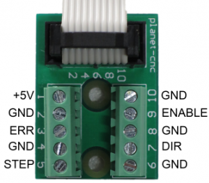
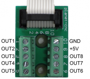
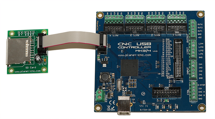
Mk3 output connector:
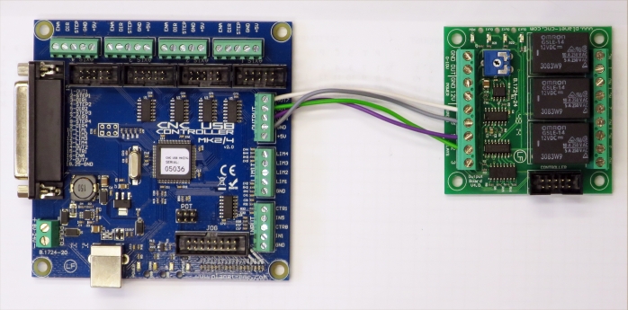
Mk2 connection:
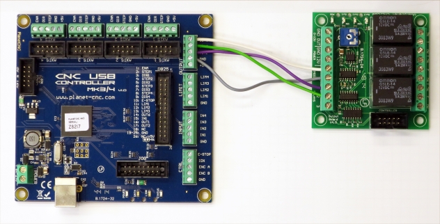
Mk3 connection:

Mk2/4,Mk3/4 and Mk3DRV:
These controllers use screw type connectors so you will need to use single wires to connect controller with output board. To know which output pin from controller is connected to which input of output board, please refer to tutorial in Step 1.
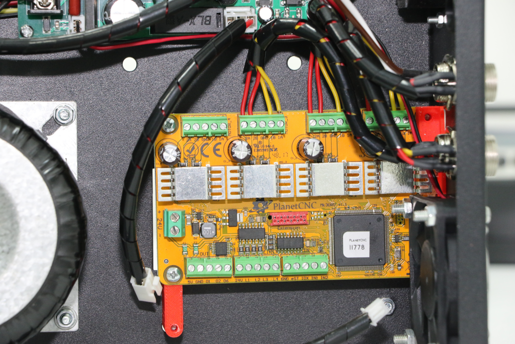
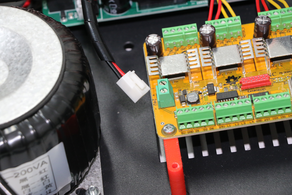
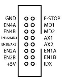
Mk3DRV output connector:
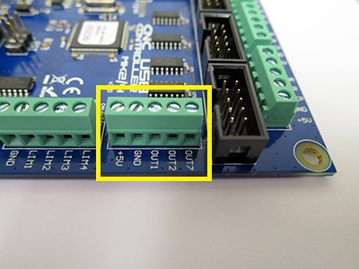
Mk3/4 output connector:

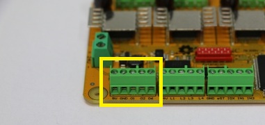
Mk2/4 output connector:
Mk2/4 connection:
Mk3/4 connection:
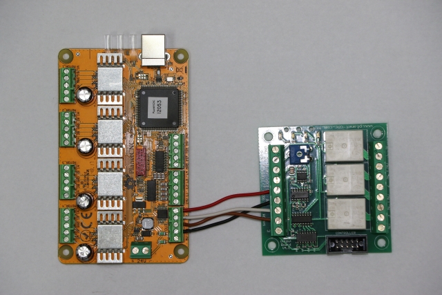
MK3DRV connection:
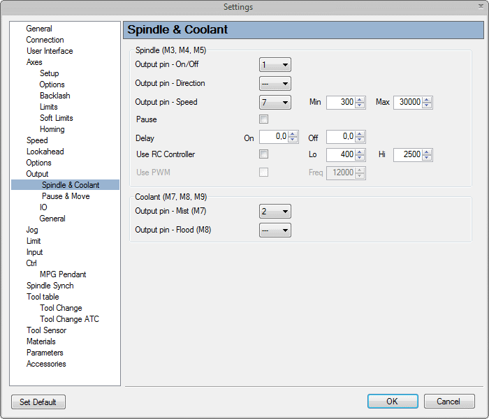
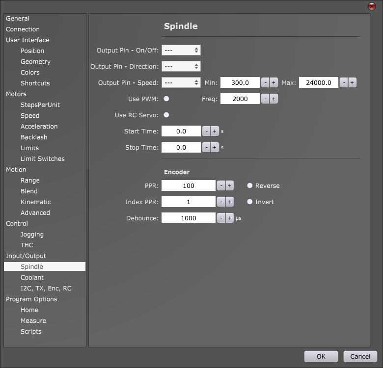
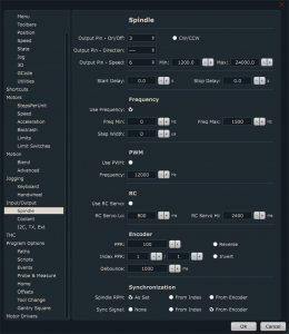
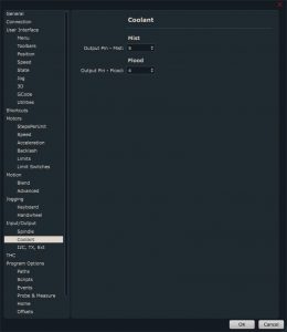
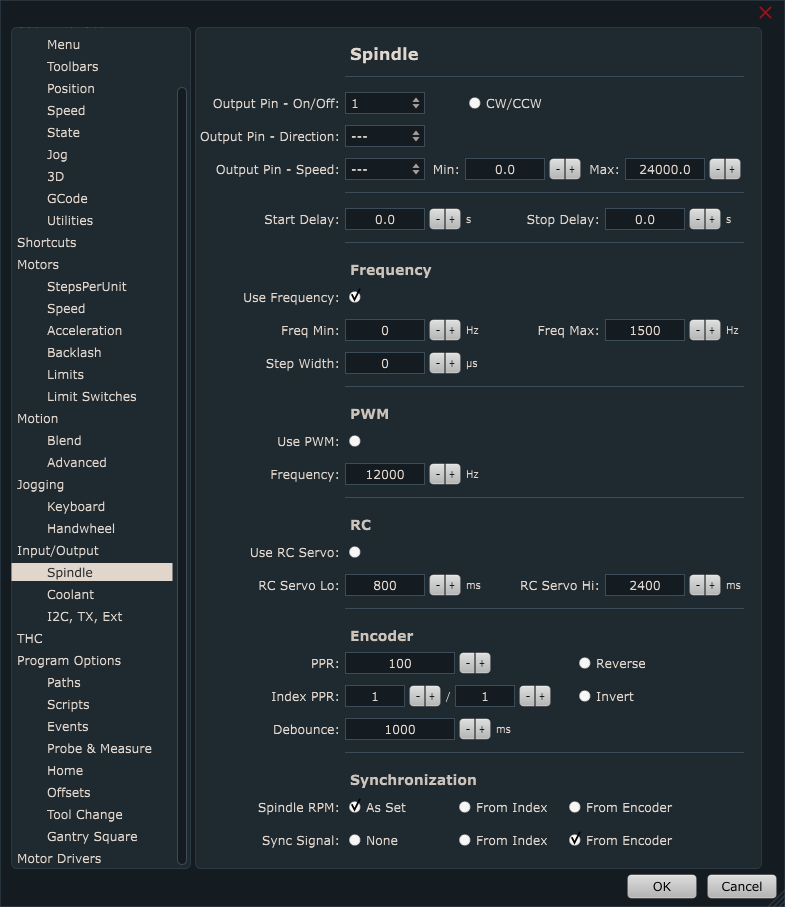
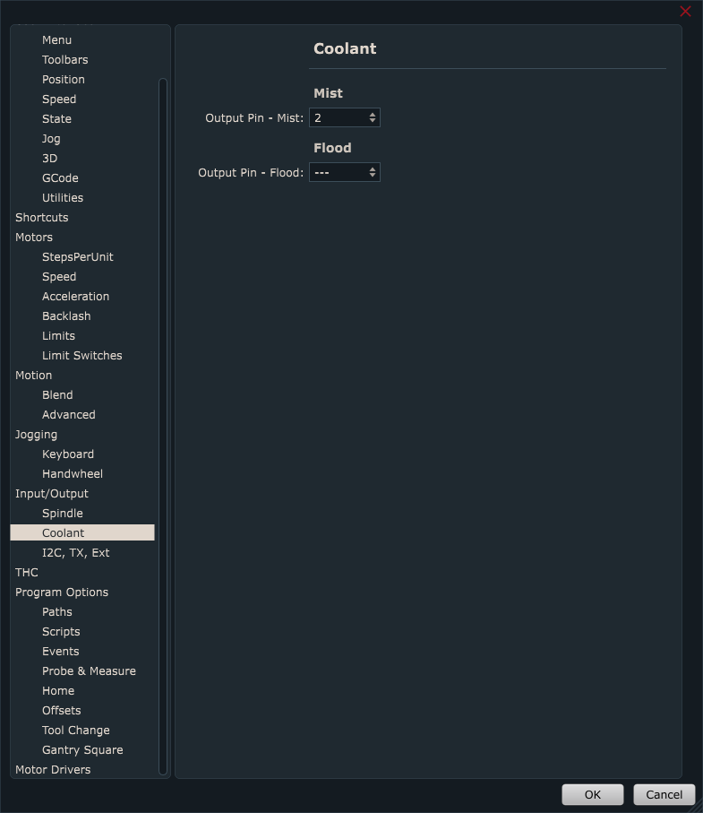
3. Configuring controllers output pins in PlanetCNC TNG software:
For Mk3 controller:
Connect Mk3 controller with output board like described above (connection for Mk3 and Mk2).
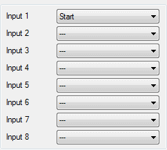
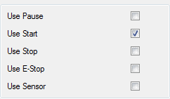
Set settings like this:
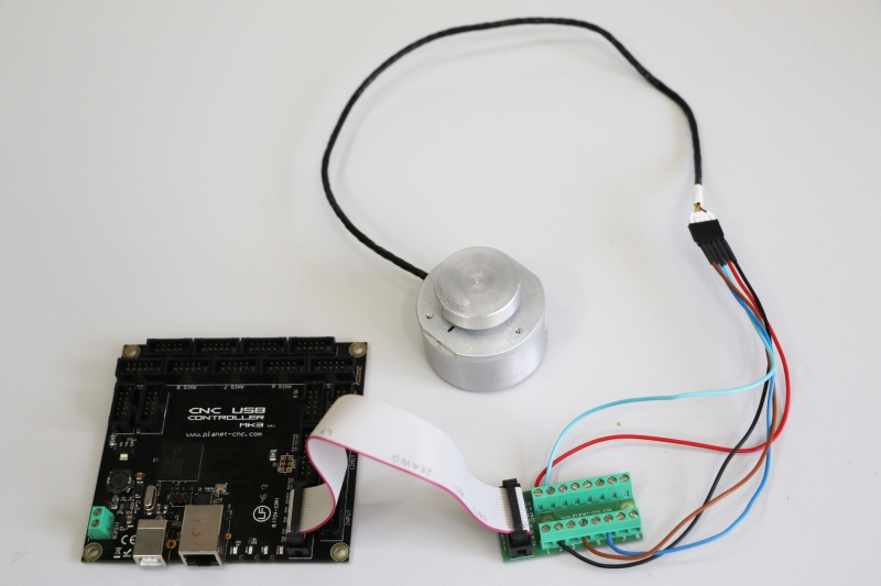
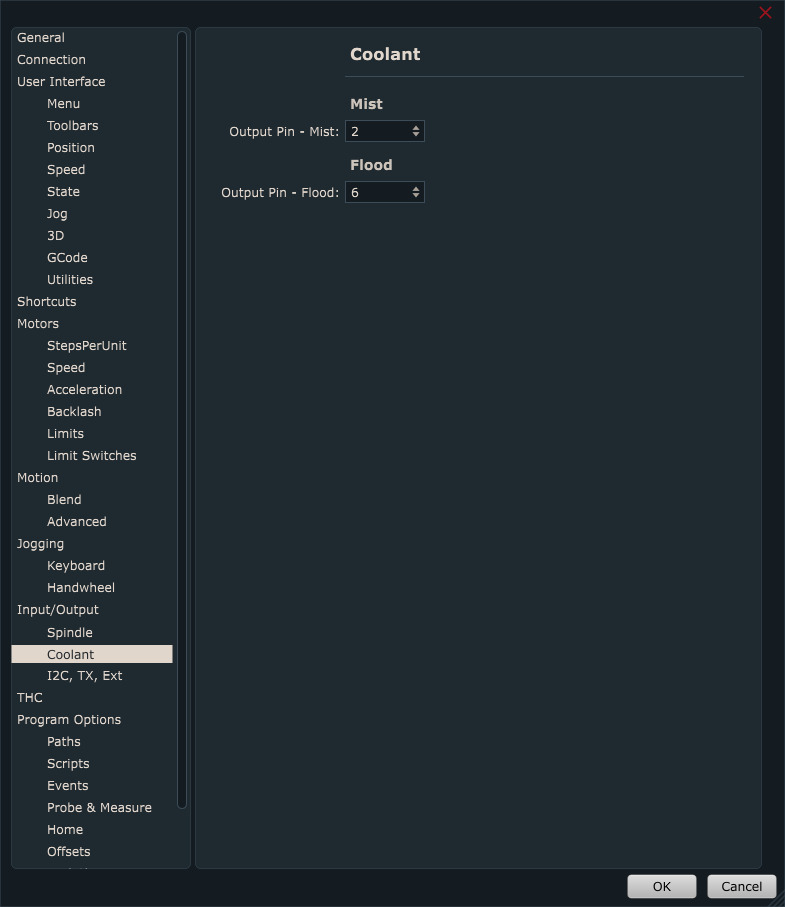
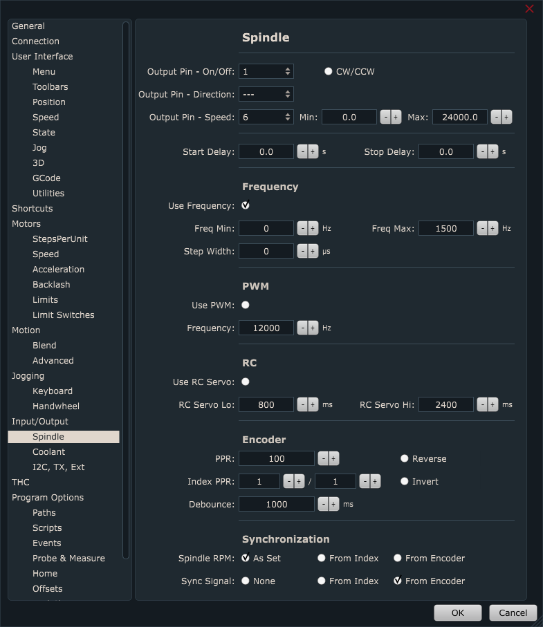
For Mk3/4 and MK3DRV controllers:
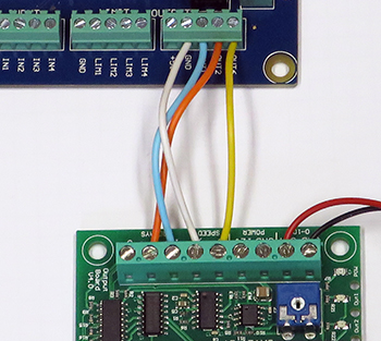
Connect Mk3/4 or Mk3DRV controller with single wires to screw terminals.
If you want to use 3 relays without the 0-10VDC output, connect output board terminals to controller like this:
“S” – not connected
“0” – GND
“1” – OUTPUT1
“2” – OUTPUT2
“3” – OUTPUT6
Set settings like this:
If you want to use 2 relays and 0-10VDC output, connect output board terminals to controller like this:
“S” – OUTPUT6
“0” – GND
“1” – OUTPUT1
“2” – OUTPUT2
“3” – not connected
Set settings like this:
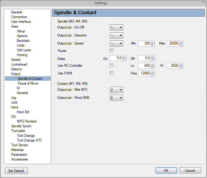
4. Configuring controllers output pins in CNC USB controller software:
For Mk2 and Mk3 controller:
Connect Mk3/Mk2 controller with output board.Do not connect terminals labeled “S”, “0”, “1”, “2” and “3”.
Set settings like this:

For Mk3/4 controller:
Connect Mk3/4 controller with wires to screw terminals.
If you use 3 relays connect output board terminals to controller like this:
“S” – not connected
“0” – GND
“1” – OUTPUT1
“2” – OUTPUT2
“3” – OUTPUT6
Set settings like this:
If you use 2 relays and 0-10V connect output board terminals to controller like this:
“S” – OUTPUT6
“0” – GND
“1” – OUTPUT1
“2” – OUTPUT2
“3” – not connected
Set settings like this:

For Mk2/4 controller:
Connect Mk2/4 controller with wires to screw terminals.
If you use 3 relays connect output board terminals to controller like this:
“S” – not connected
“0” – GND
“1” – OUTPUT1
“2” – OUTPUT2
“3” – OUTPUT7
Set settings like this:

If you use 2 relays and 0-10V connect output board terminals to controller like this:
“S” – OUTPUT7
“0” – GND
“1” – OUTPUT1
“2” – OUTPUT2
“3” – not connected
Set settings like this: