How can I use Mastercam
Milling some wooden part using Mastercam
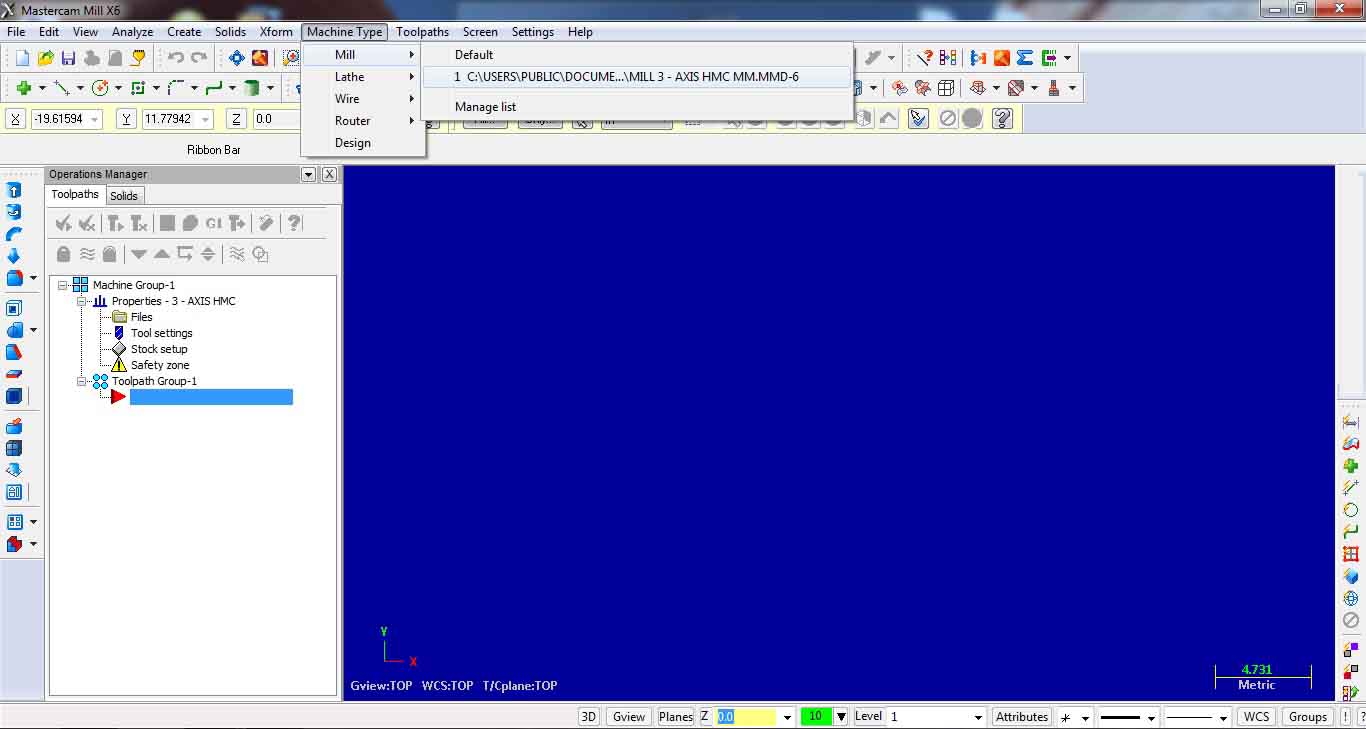
1. SELECTING AND SETTING MACHINE DEFINITION:
Chose Machine type – Mill – Manage list… from machine definition menu select MILL – 3 AXIS HMC.MMD-6.
Add and select.
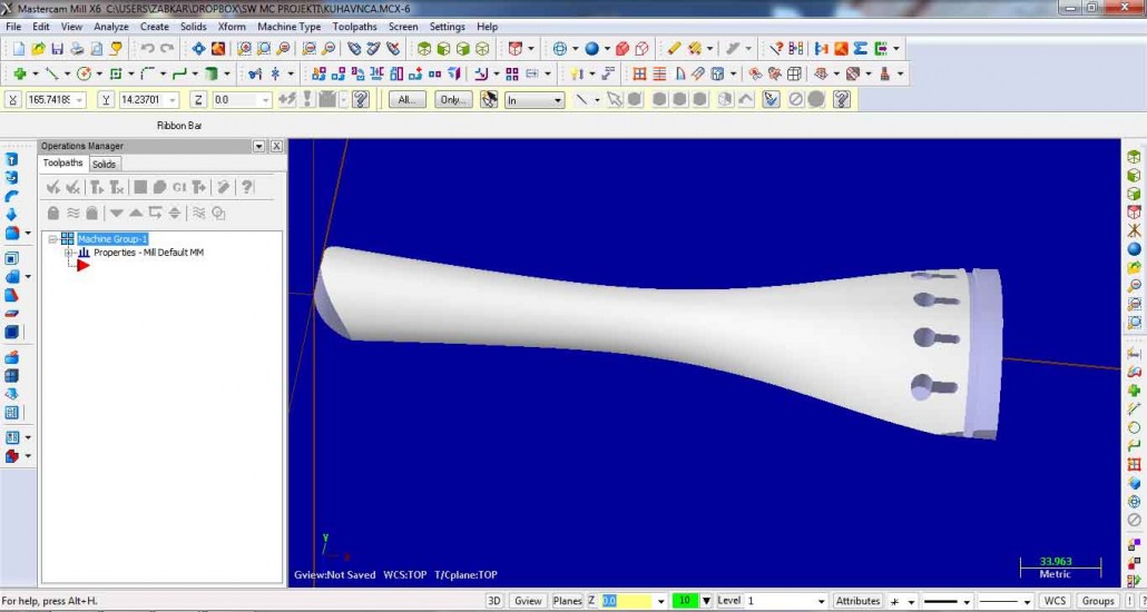
2. IMPORTING AND PREPARING PART:
Open part file (File – Open). It is recomended that file is in step format.

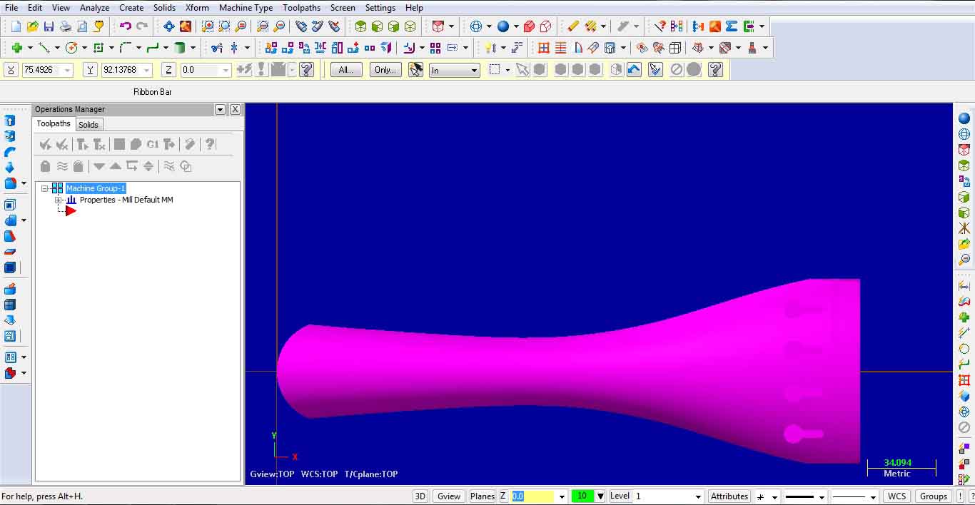
Select WCS TOP – top work coordinate system, usually selected for milling top side of workpieces on 3-axis milling machines.
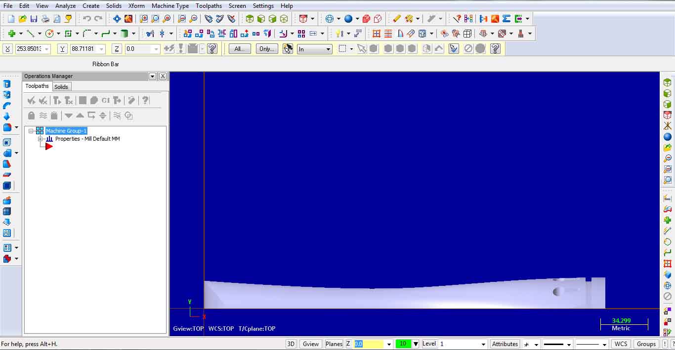
Use commands Xform translate to move part to desired origin position (use F9 key to show/hide coordinate axes)
and Xform rotate to rotate the part in position, where WCS and Gview (graphic view) will both be set to TOP.
When performing rotation of the part, one of the standard views (Top, Front, Right…) should be selected.
Before rotation: Gview is not in correct orientation, because only a side way of the workpiece could be machined this way.
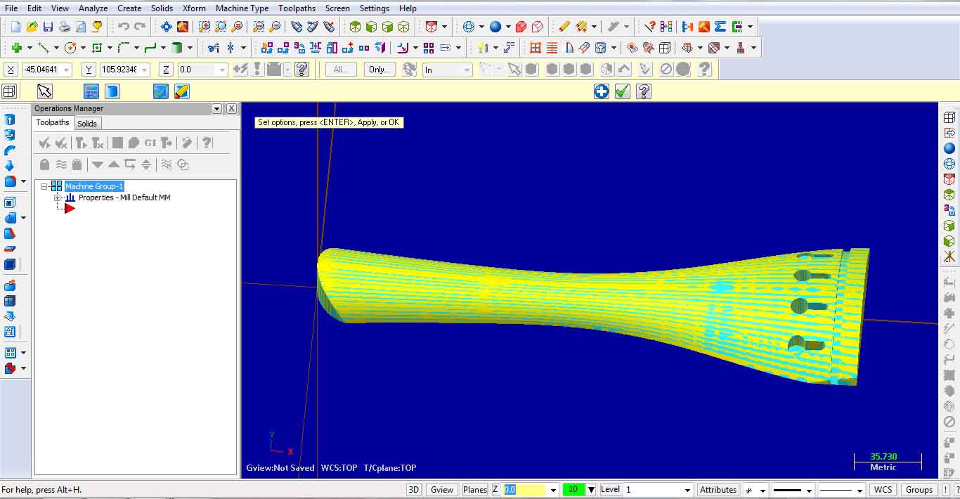
After rotation: WCS and Gview both set to TOP and whole surface could be machined
.
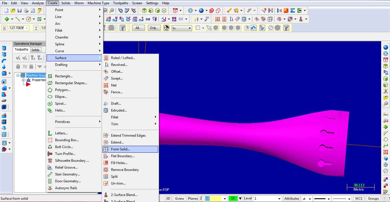
After the part has been moved and oriented, it is recomended that surfaces and edge curves are
created from solid part: Create – Surface – From solid… and we chose to delete solid body. For creating edges we chose: Create – Curve – Curve on all edges.
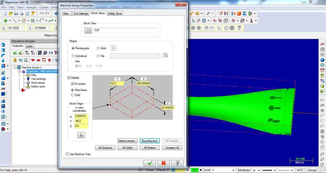
3. DEFINING STOCK:
Under machine group select Stock setup to set stock dimensions. There are many possibillities. Bounding box is best one.
4. CREATING TOOLPATHS:
Depending on milling application (Contur, Drill, Pocket, Face or Surface rough/finish), we chose the
right toolpath type under Toolpaths. It is possible that some additional chain geometry should be drawn to the part, like in this case:
In this example Facing is the first operation to perform face milling of the workpiece.
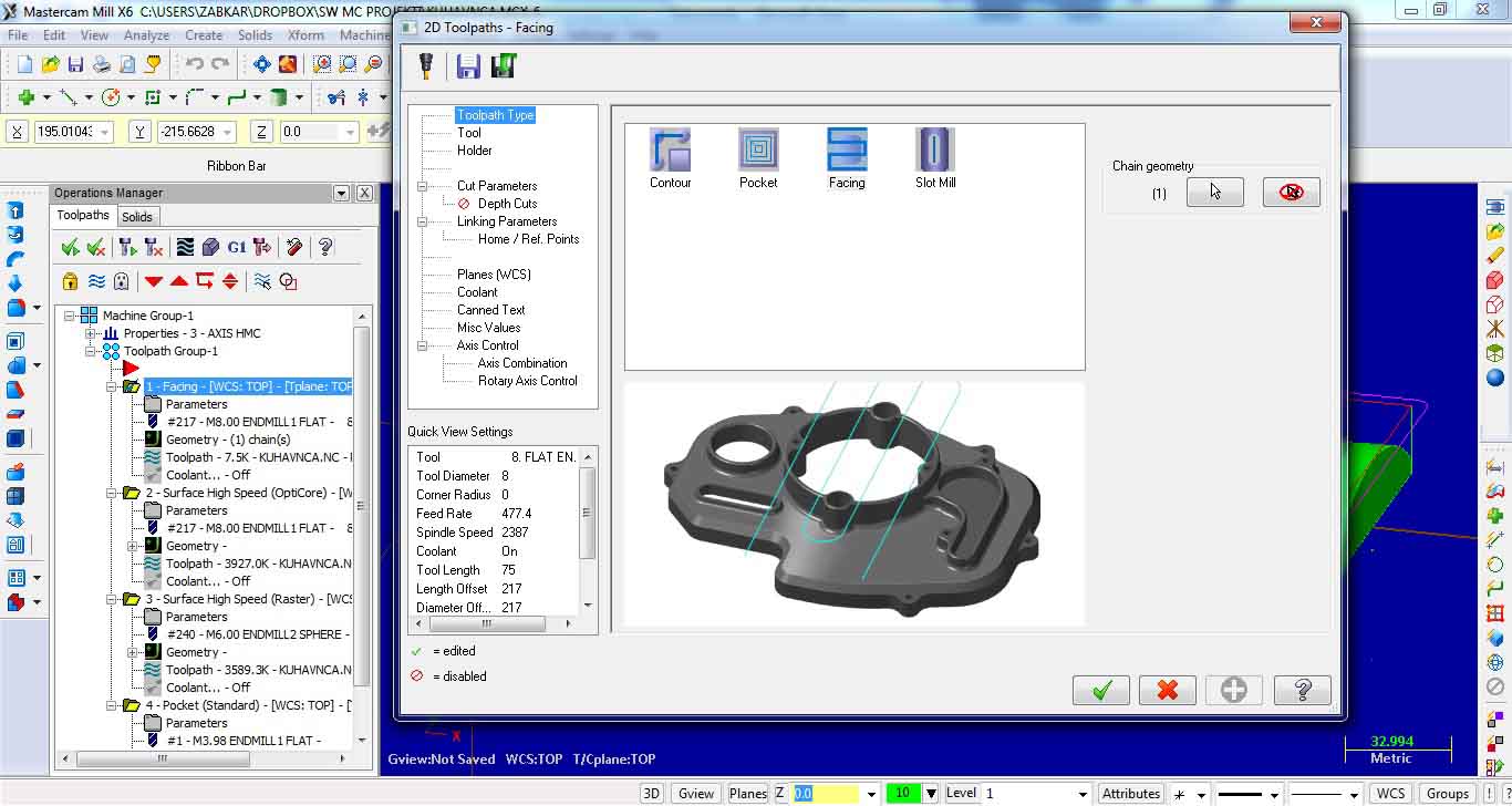
We could set different parameters from the Toolpaths Facing window. Most important are:
Tool: Type (from library), Feed rate and Spindle speed
Cut parameters: Style, Overlap, Maximum stepover, Stock to leave
Linking parameters: Retract, Feed plane, Top of stock, Depth… When adjusting those values there are two options:
Absolute – Z values are in respect to the WCS origin, Inremental – Z values are in respect of the shape.
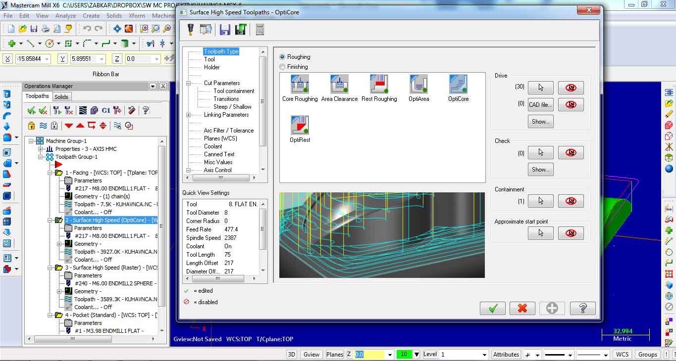
Second milling operation is surface high speed Opti core for roughing.
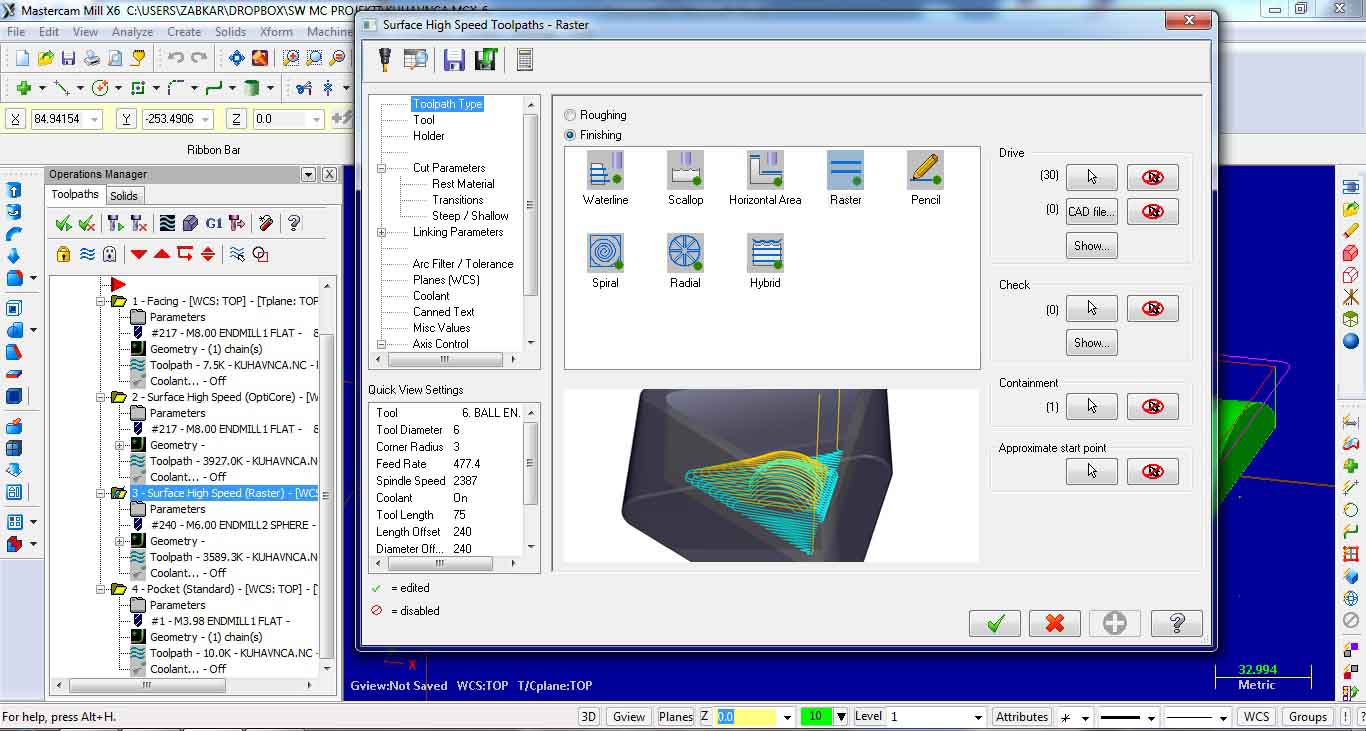
Third milling operation is surface high speed Raster for finishing.
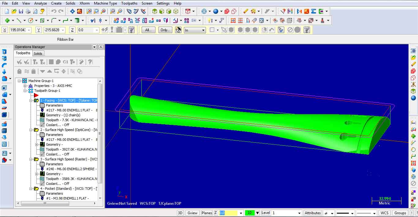
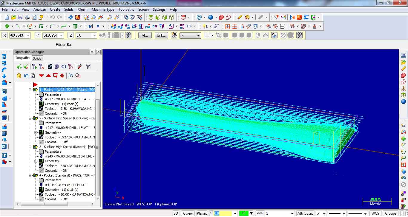
The last one is Pocket standard for making pocket holes. Image shows all toolpath operations performed to machine the selected part.
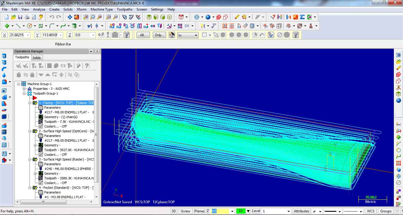
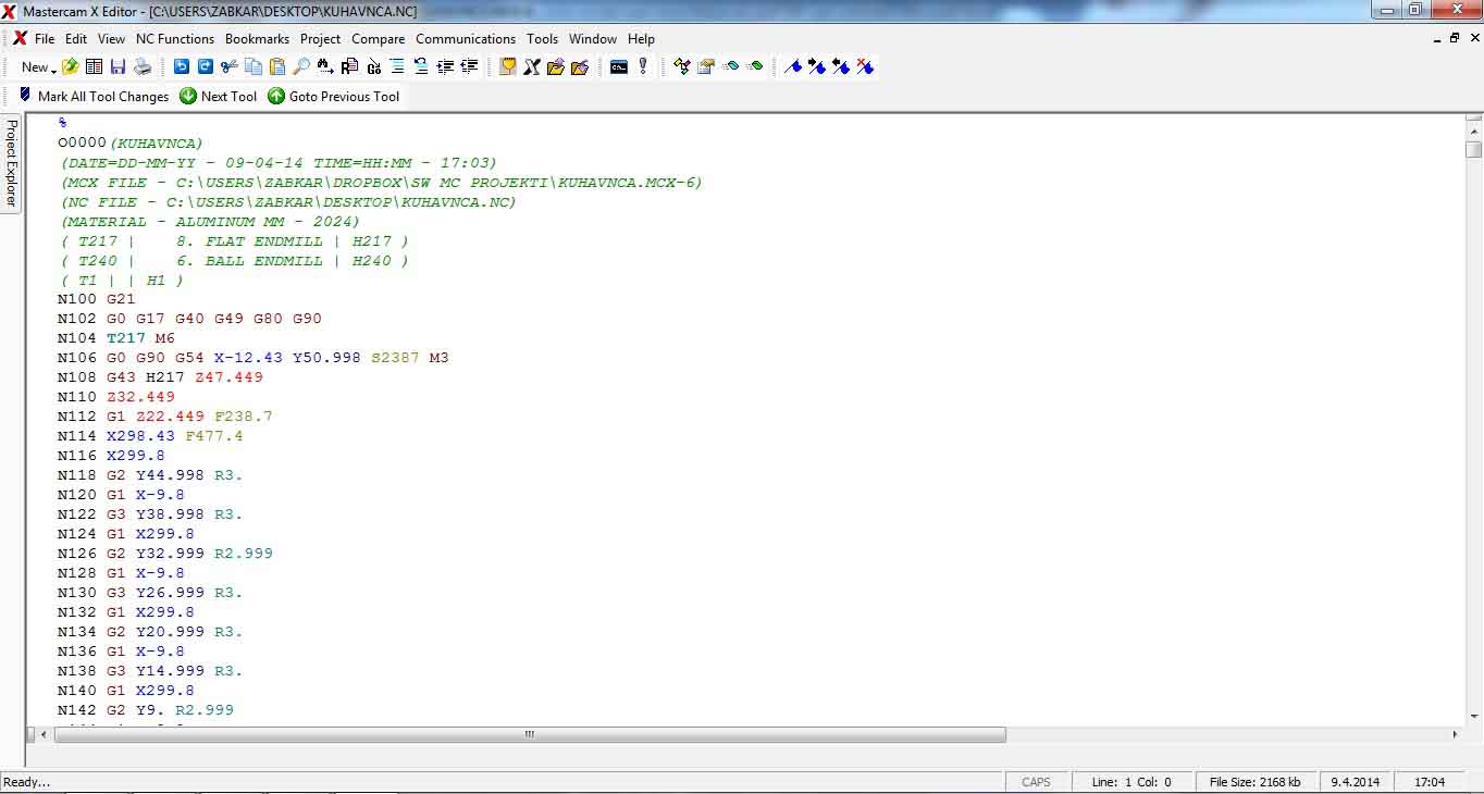
All toolpath operations can be simulated and verified under Operations Manager, using different control buttons. G1 button is for postprocessing the G code.
5. POSTPROCESSING:
Different milling operations can be joined (by selecting) and postprocessed together. In example: rough facing and rough surface opti core, which contains the same tool.