CNC machine semaphore application, using expressions (Expr.txt) – Part 2

What is a State Machine and how it is used?

If you google State machine, this would be the average result more or less:

“A state machine is a behaviour model. It consists of a finite number of states and is therefore also called finite-state machine (FSM). Based on the current state and a given input the machine performs state transitions and produces outputs.” 

Sounds exactly what we need for our application doesn’t it?  5 states, which can transition one from another based on the pre-defined conditions.

Each semaphore state has its outputs and inputs.  State outputs are semaphore light configurations where specific relay output will be activated. State inputs are conditions that will cause the state transitions.

Both will be described in detail in Part 3 of this tutorial.


What is an Expr.txt file and how it is used?

  • Expr.txt is a file which contains functions that are evaluated by PlanetCNC TNG expression evaluator.
  • it can be very practical for PLC type applications where periodical evaluation is necessary or for program events
  • Expr.txt file can contain and use vast array of expression functions, parameters and other commands supported by PlanetCNC TNG
  • Expr.txt file is located in the profile folder of TNG software
  • Profile folder can contain multiple Expr.txt files. Specific Expr file naming convention is available for better distinction. e.g.: Expr_Semaphore
  • If multiple expr files use same function, then function will be called first in first file and only then the with the next file
  • Local variables(e.g. name convention of local variables: red_light, global variables: _red_light ) have scope only within the parent Expr file.
  • Each Expr file contains functions that are marked with symbol #.
  • Each function begins with symbol # and ends with the next # symbol.
  • Each expr file can use built-in functions that are related with program events


Built-in Expr functions:

  • #OnInit -> When TNG software is started/initialized, code under this function will be executed.
  • #OnShutdown -> On PlanetCNC TNG software shutdown request, code under this function will be executed, then TNG will shutdown.
  • #OnStart -> On NC program Start event, code under this function will be executed.
  • #OnEnd -> On NC program End event, code under this function will be executed.
  • #OnStop -> On NC program Stop event, code under this function will be executed.
  • #OnEStop -> On Estop event, code under this function will be executed.
  • #OnJog -> On Jogging event, code under this function will be executed.
  • #OnWheel -> On handwheel event, code under this function will be executed.
  • #OnCmd -> On MDI command event, code under this function will be executed.
  • #Loop          -> this loop is executed every 83ms, or the value of refresh rate set in settings, under: File/Settings/User Interface/Refresh Rate
  • #Loop5       ->this loop is executed every 5s
  • #Loop15      ->this loop is executed every 15s
  • #Loop60     ->this loop is executed every 60s
  • #Loop300  ->this loop is executed every 300s


CNC machine semaphore application, using expressions (Expr.txt) – Part 1

For this multi-part tutorial we will create CNC machine semaphore(signal tower lamp).

We hope that this tutorial will serve as a good example on how to set application goals and requirements as also on how to define the tools and solutions  for achieving them, while using powerful tools and flexibility of PlanetCNC motion control system.


How to begin?

First we need to clarify and define application requirements.

Semaphore application requirements

We want:

  • to use a semaphore with 5 lights.
  • Each light with different colour will visually represent dedicated machine state.
  • Combination of two active lights is allowed. This applies when NC program is running and pause is initiated.
  • Additionally, alarm should be activated if, at the beginning or during the program execution, front door of machine enclosure is open(ed) or pressure sensor is activated. Pressure error will be able to initiate alarm state also in Idle state.
  • In case of alarm, system should prevent or stop program execution.
  • Play siren sound to notify CNC operator.
  • Alarm notification is displayed on the main screen and at the status bar.
  • Alarm state needs to be reset. Hardware Reset button will be used.
  • If alarm is not reset and system is shut down, system will notify user to reset any pre-existing alarm at the system startup.


Machine states are:

  • Estop state
  • Idle state
  • Run state
  • Pause state
  • Alarm state


State description:

Estop

Estop state indicates that estop has been activated either using a PC keyboard key, controller estop pin (e-stop button) or Error pin indicating a motor driver fault.

This state will be indicated using active RED LIGHT on the semaphore.


Idle

Idle state indicates that machine is turned ON and connected with PC. Machine in Idle state does not perform any motion.

This state will be indicated using active YELLOW LIGHT on the semaphore.


Run

Run state indicates that CNC machine is executing the NC program.

This state will be indicated using active GREEN LIGHT on the semaphore.


Pause

Pause state indicates that machine is executing NC program, however program pause has been initiated, meaning program execution is on hold.

This state will be indicated using active ORANGE LIGHT in combination with active GREEN LIGHT(Run state) on the semaphore.


Alarm

Alarm state will indicate if CNC machine enclosure doors are open, at the start of program or during the program execution. So, if doors will be opened in any other state than Run, there is no need for an alarm.

This state will be indicated using a  BLUE LIGHT on the semaphore. In this state, we will also use siren sound alarm.


What hardware will we use?

So, we need to control 5 lights on the semaphore, and read one enclosure door switch. Meaning we need to occupy 5 digital outputs and 1 digital input of our MK3 controller.

But, digital input and output pins of controller are a precious commodity.  It would be better to use these pins for some other purpose.

More economic approach would be the use of ExtInOut board. This board expands the number of inputs and relay outputs used with controller by 8, respectively.


-ExtInOut board relays will control the semaphore lights, while one of the inputs will be used to evaluate CNC front door switch and Alarm reset button: ExtInOut board

-PlanetCNC Mk3 motion controller and EXT interface will be used for communication with external ExtInOut board: Mk3 controller

-Semaphore lights will be simulated with normal LED’s. If a real semaphore device would be used, integration would not be much different.

Programming the application

For a clearer and effective programming, we will use a concept called State Machine. Its functionality is suitable for the type of our application.

Drawing a flowchart will help us with visualization of such state machine and better overview of state definitions and state transition conditions.

Since we need constant and responsive background evaluation of various parameters and control of relay outputs, all our code will be included in the Expr.txt file.


In part 2 we will describe our state machine and Expr.txt file

Tool change settings in PlanetCNC TNG software

Prior following this tutorial we recommend that you perform tutorials below:

How to measure tool offset with fixed tool sensor in PlanetCNC TNG software
How to measure work position with movable sensor in PlanetCNC TNG software


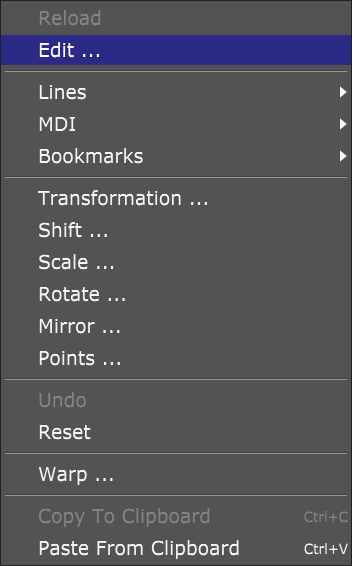
Tool change settings are located under File/Settings/Program Options/Tool Change:


Tool Change settings are divided into three setting groups: Tool change – General, Tool offset and ATC*.
*Tool Change ATC group of settings will not be described and used in this tutorial. ATC configuration is described in depth in the PlanetCNC TNG user manual.


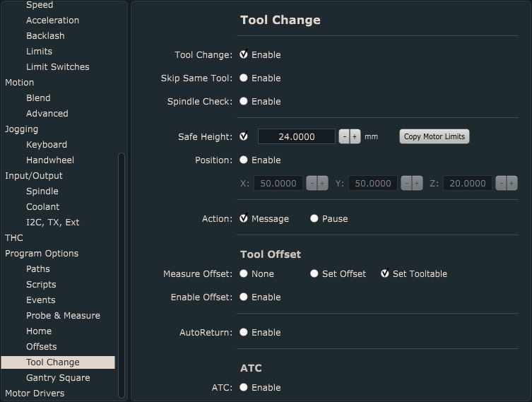
Tool Change – General settings group:

Here we set how we want our machine to “behave” during Tool change.

Tool Change – Enable:
This enables tool change procedure.

Skip Same Tool – Enable:
If tool with number “n” is already mounted then Tn M6 g-code will be ignored and tool change will not occur.

Spindle Check – Enable:
At the beginning of tool change procedure, spindle will be turned OFF (if it was ON prior)and when tool change procedure is completed, spindle will be turned ON.

Safe Height:
This value represents the machine Z axis value to which machine will ascend when tool change occurs. You enable it with a check on radio button. If Position is enabled, machine will travel to its XYZ position at Safe Height value.

Position:
This is XYZ machine position value to which machine will travel once the tool change is initiated. This position is final position where you will change your tool.

Action – Message:
When tool change occurs, tool change message will be displayed, informing user of current and a new tool number. Until user confirms the OK button, motion will be paused.

Action – Pause:
When tool change occurs, pause will be activated. Machine travels to tool change position and motion is paused. This way user can safely change the tool and resumes program execution.

Both enabled:
When tool change occurs, message will be displayed first, after message is confirmed, pause will be activated.


Tool Offset settings group:

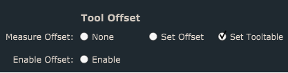
Measure Offset -None:

Tool length will not be measured and stored. This is suitable when user already has created and populated its tool table. Each tool in the tool table has already been measured and its tool offset value has been stored in the tool table.


Measure Offset -Set Offset:

If your machine and tool change process uses fixed tool sensor to measure tool length offset you enable this option. After tool offset measurement is completed, tool offset value will be set and stored.


Measure Offset -Set Tooltable:

If your machine and tool change process uses fixed tool sensor to measure tool length offset you enable this option. After tool offset measurement is completed, tool offset value will be set and stored in the tool table.

This comes handy when your tool change gcode uses such format: Tn M6 G43 -> G43 command will activate tool offset from tool table previously set and stored during tool offset measurement.


Enable Offset:

With your tool offset measured and set, you need to activate it. To activate tool offset value you need to enable this option.

This comes handy when your tool change gcode does not use G43.


Auto Return:

This depends on your g-code. By g-code standard g-code return moves should be in g-code program but are often not.
Here is example:

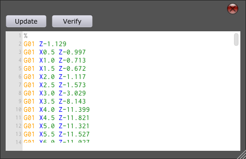
This is correct g-code:

G01 X0 Y0(start position)
G01 X10 Y0(cut to X10 Y0 with first tool)
T2 M6 (change tool tool with auto return off)
G01 X10 Y0(return to last position)
G01 X20 Y0
G01 X30 Y0

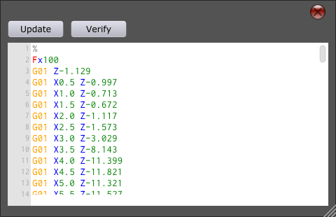
This is wrong but often used:

G01 X0 Y0(start position)
G01 X10 Y0 (cut to X10 Y0 with first tool)
T2 M6 (change tool with with auto return on)
(no need for G01 X10 Y0 line because of auto return)
G01 X20 Y0
G01 X30 Y0


TOOL CHANGE PROCEDURE

Here, we will describe what prior settings configuration need to be performed before we set our workpiece and work offsets.

We will also describe the tool change procedure itself. So based on our tool change settings configuration, what will be the machine motion sequence during tool change procedure.


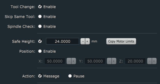
Below is the tool change setting configuration that will be used for this example.

The requirements are :
– If Tn M6 code is present in the program, tool change procedure should be executed -> Tool Change > Enable

-If spindle is in ON state and tool change command is executed, spindle is turned OFF and once the tool change procedure is completed, spindle will restore its ON state  -> Spindle Check > Enable

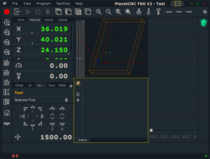
-Once tool change command is executed, machine will travel to tool change position at Safe Height value -> Safe Height > 24.15mm

-Machine position where we will change the tool will be at X: 50mm Y:50mm and Z:20mm -> Position > Enable > X50; Y50; Z20

-When machine arrives to tool change position, motion should be paused and notification is displayed. Once we change our tool, we confirm the dialog and proceed with tool offset measurement. -> Action > Message

-Tool offset will be measured for each individual tool during the tool change procedure. For this, fixed tool sensor will be used. -> Tool Offset > Measure Offset > Set Offset

-After tool offset value is set and stored, we want to activate tool offset -> Enable Offset > Enable


Here are the steps, that should be performed in chronological order before we start our gcode program that uses multiple tools and therefore tool change procedure:

1. Homing procedure. Machine should be referenced so that we are sure that machine uses correct positions.

Click: Machine/Home

2. Mount and set the tool that you will use as first tool in your main gcode program. 

2.1 Type into the MDI: Tn M6.

2.2. Machine will now perform tool change procedure:

-Machine will move to position of tool change at X50, Y50 and Z 20 at Z = 24.15mm position

-Software will open a dialog which will inform us of the new tool number. Motion will be paused, and we can now mount our first tool into spindle.

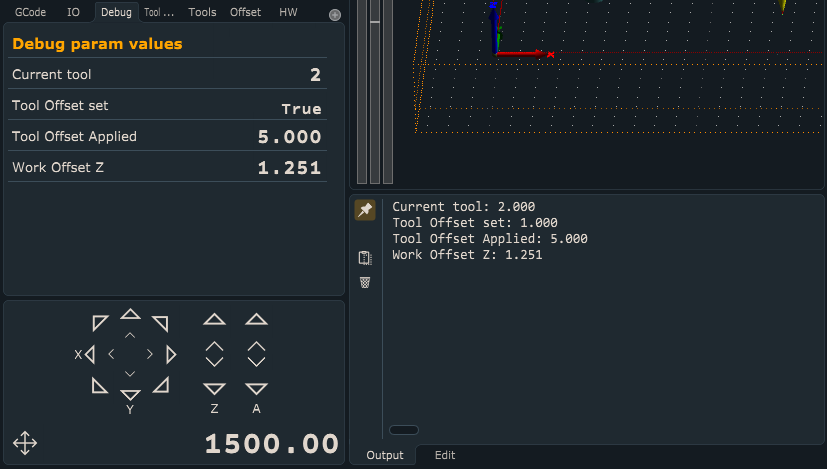
-Once we confirm the dialog, machine moves to position of fixed tool sensor and measures tool offset. Machine will return to position where the tool change command was executed.

-In software, new tool number and its tool offset value will be set and activated.

3. Set Work Position XY = 0 of your workpiece.  

Click the left toolbar button Work Position/Axis To Zero/XY  or via Machine/Work Position/Axis To Zero/XY

4. Set Work Position Z = 0 of your workpiece. You can do this manually or you can use measure height Z procedure with movable sensor.

Click the left toolbar button Work Position/Axis To Zero/Z  or via Machine/Work Position/Axis To Zero/Z

To use movable sensor click the left toolbar: Work Position/Measure Height or via Machine/Work Position/Measure Height


So once we mount, measure and set our first tool, and after we set the XY and  Z axis work offsets, we can start our gcode program:

1. Start your gcode program

2. Tool change for second tool is executed. Steps are the same as at point 2. 

3. Machine will continue with program execution after the tool change gcode.


Program debugging in PlanetCNC TNG software

Debugging tools in PlanetCNC TNG

For purposes of program observation or debugging, user can use PRINT and LOG commands, output window and state tabs for parameter value display. G-code ref manual will also come very handy.

Output window

To show/hide output panel in PlanetCNC TNG main window, click the middle square symbol in the upper right corner:

Output window will appear at the bottom middle section of the main window:


PRINT and LOG commands can be inserted within main gcode or script gcode at appropriate program lines. With output window, printed values can be then observed, while LOG command creates its own file that can save desired parameter values.

Example:

We want to observe values of the following parameters:

_current_tool
_tooloff
_tooloff_z
_workoff_z

These parameters can be displayed in Output window, Custom state tab or separate LOG file:


More on PRINT, LOG commands and how to create your own state tab can be found on links below:

PRINT: https://planet-cnc.com/using-print-command-with-planetcnc-tng-software/

LOG: https://planet-cnc.com/using-log-command-with-planetcnc-tng-software/

State tabs: https://planet-cnc.com/create-custom-tabs-planetcnc-tng-software/


Gcode in PlanetCNC TNG software

PlanetCNC TNG is a motion control software intended for control of CNC machines. As a standard, g-code is used as native programming language.

PlanetCNC TNG software processes gcode program and sends series of commands to motion controller. Controller interprets these commands and arranges coordinated machine motion.


Gcodes

G-code commands can be divided into multiple groups which differ from one another based on functionality and intended use.

Single G-code line, aka block, can include commands for modal state configuration, machine motion, program control and data manipulation, or peripheral control.
PlanetCNC TNG supports also gcode functions, expression functions, parameters, operators etc…


List of Gcode groups:
G-codes (G21,G17,G90, G00,G01…)
M-codes (M3,M5,M6…)
Other codes (F,S,T)
O-words (SUBROUTINE, CONDITION…)
Comments (LOGCREATE,LOG…)
Operators (+,-,EQ,GT,AND…)
G-code functions (Exists, Sin, Cos, Inc, Dec…)
Expression functions (infoIsInitialized, infoMachinePosition…)


Complete list of gcode commands and system parameters is available in PlanetCNC TNG G-code reference manual. This document is located in Doc folder of PlanetCNC TNG main installation folder. 


Simple g-code programs (i.e. toolpaths) can be easily written manually. For this purpose we recommend that users gets at least familiar with g-code. Get to know groups of g-code commands, syntax, format and programming guidelines. Even if user does not have an intention of manually writing his g-code programs, it can be in great help when debugging and understanding program and machine behaviour.


We really encourage our users that they explore PlanetCNC TNG scripts, they are a really great source for discovering different types of gcode programming and programming approaches. Single script code can offer a lot of new knowledge for a curious CNC beginner as also for a well rounded programmer.

More about accessing and configuration of scripts can be read here:
Accessing script files in PlanetCNC TNG

Installing PlanetCNC TNG software on Raspberry Pi 3

You will need:
– Raspberry Pi 3 Model B (or B+)
– Monitor with HDMI cable
– Mouse and Keyboard
– Power supply
– 8GB SD card (16GB and 32GB should also work, 64GB or more will not work)

We used NOOBS version 2.8.2 in this tutorial but it should also work with newer versions.

1. Download NOOBS from here:


You will get almost 2GB large file named “NOOBS_v2_8_2.zip”

2. You need to format SD card. We suggest that you use “SD Memory Card Formatter 5.0” which you can get here:
https://www.sdcard.org/

– Download “SD Memory Card Formatter 5.0”.
– Follow the instructions to install the software.
– Insert your SD card into the computer or laptop’s SD card reader and make a note of the drive letter allocated to it, e.g.
– In SD Memory Card Formatter, select the drive letter for your SD card and format it.

3. Extract files from NOOBS zip file to SD card.

Your SD card contents should look like this:

4. When this process has finished, safely remove the SD card and insert it into your Raspberry Pi. Connect monitor, mouse and keyborad and power up Raspberry Pi.
After few moments selection dialog will appear.

Select “Raspbian (full desktop version)” and click install. Confirm overwriting SD card and wait for Raspbian to be installed. It might take a while.

Another tutorial for Raspbian installation using NOOBS is here:
https://projects.raspberrypi.org/en/projects/noobs-install

5. When installation is finished you will get nice welcome screen and Raspbian will ask you to set country, time zone and password.
You do not have to set password if you do not want it.

If connected to internet it will download and install updates. If not then skip this step.

When finished it will ask to reboot.

After reboot you are ready to install PlanetCNC TNG.

6. First we will modify “config.txt” file.
– Open terminal.

– Type “sudo nano /boot/config.txt”

– GNU nano will apear. Scroll to bottom of file and type:
gpu_mem=128
dtoverlay=vc4-kms-v3d

– If you have black border on your monitor then locate line “disable_overscan=1” and uncomment it.

– When done exit GNU nano by clicking Ctrl+X and confirm saving modified buffer.

7. Reboot Raspberry Pi

7. After reboot we will install PlanetCNC TNG. Create subdirectory “PlanetCNC” in your HOME directory.

8. Download or copy ‘PlanetCNCPi-TNG_(version).tar.gz’ tarball to subdirectory.

9. Extract ‘PlanetCNCPi-TNG_(version).tar.gz’ tarball with “tar -xvf PlanetCNCPi-TNG_*.tar.gz”

10. Run installation script with “sh install.sh”

If you set password then you will be asked to enter it. After instalation completes PlanetNCC TNG will start automaticaly.

11. You can close all windows. There should be PlanetCNC icon on desktop. Double click will start PlanetCNC TNG.

Using ExtOut board with PlanetCNC TNG software

This tutorial will help you configure ExtOut board related settings in PlanetCNC TNG software.


ExtOut board settings are located under File/Settings/Input&Output/I2C,TX,Enc,RC.

Under Ext section insert value 10000 for Frequency and enable Invert option for SEL1 Pin:

Related g-codes:

M64 – Output ExtOut

Usage: M64 H Q <L>

– H = ExtOut SSEL value (1 or 2)
– Q = data send to ExtOut
– L (optional) = number of bytes send to ExtOut

M64 H Q E <L>

– H = ExtOut SSEL value (1 or 2)
– Q = parameter number of first data location
– E = data count
– L (optional) = number of bytes send to ExtOut

M64 H P Q <L>

– H = ExtOut SSEL value (1 or 2)
– P = bit position
– Q = zero for Off, otherwise On
– L (optional) = number of bytes send to ExtOut

M64 H L0

– H = ExtOut SSEL value (1 or 2)
– L = zero bytes send to ExtOut


Examples:

In PlanetCNC TNG install folder locate and open Samples folder. Open Tutorials folder and locate files: M64ex1.txt, M64ex2.txt, M64ex3.txt, M64ex4.txt, M64ex5.txt, M64ex6.txt

These sample g-code programs describe various uses of M64 g-code and ExtOut board.


Using MPG pendant with PlanetCNC TNG software

This tutorial will help you configure MPG pendant related settings in PlanetCNC TNG software.

MPG settings are located under File/Settings/Control/Jogging -> Handwheel

Parameter description:

Enable:
Enables use of encoder for purposes of jogging when using MPG pendant(used with Mk3 MPG adapter) or standalone encoder. For more info regarding controllers encoder inputs please read Mk3 and Mk3/4 controller user manual.
Note: These settings apply to encoder connected to controller header CTRL pins: EN1A and EN1B

PPR:
Enter PPR value (parts per revolution) of your MPG encoder. Usually around 100PPR.

Reverse:
Reverses direction of jogging when MPG encoder is used for jogging.

Step Mode 0-6:

You can configure seven modes of jogging when using MPG pendant with PlanetCNC TNG. To select between modes you use MPG hardware switch(x1, x10, x100).

Each step mode can be configured either as Speed Factor or as Step Distance.
If radio button is left unchecked Speed Factor mode will be used, if you enable radio button , Step Distance mode will be used.

Speed Factor:
Encoder wheel will be translated into motion using Speed Factor value.
Inserted value is speed factor which can behave as prescaler or multiplication of MPG encoder wheel rotation.

For example, Speed Factor of value 0.1 is used when you need fine tuning of axis motion.


Step Distance:
Rotation of encoder will jog machine for distance that is set with Step Distance.

Please note:
With PlanetCNC MPG pendant hardware switch you can select only between Step Mode 1, Step Mode 2 and Step Mode 3.

So when you are using using PlanetCNC MPG pendant, configure only Step Modes 1,2 and 3.

Machine jogging with PlanetCNC TNG software

For purposes of machine jogging, user can use on screen jogging keys, PC keyboard keys or external jogging keyboard.


On-screen jogging keys:

Click the cross button next to jogging speed window:
 
Cloud with jogging keys will appear:
Jogging keys can appear permanently on main screen if you set:
File/Settings/User Interface/Jog Panel -> enable “Fixed”. You can choose among XY Cross, UV cross or default keys layout.:

Default keys layout:

XY Cross layout:

PC keyboard keys:

PC keyboard keys used for jogging  need to be configured in settings File/Settings/User Interface/Shortcuts -> under Jog chapter. Under Code, set keyboard keys you wish to use:


External jogging keyboard:

First under IO tab observe which jogging keyboard keys activate which JOG input.
Then in File/Settings/User Interface/Shortcuts -> under Jog and Pin set designated jog input pins:

Jog1 (X-),Jog2 (X+),Jog3 (Y-),Jog4 (Y+),Jog5 (Z-),Jog 6(Z-)
Since external jogging keyboard also supports Shift key, which in combination with any other jogging key initiates step Jog motion, you should set these shortcuts also:

How to use “Program Edit” feature in PlanetCNC TNG software

Sometimes our NC program does not perform quite as we plan. Many times just a small correction of g-code does the trick and for this we need to edit our NC program.
For this purpose you can use built-in “Edit” feature.

Edit feature is located under Program menu.


When Edit feature is active, window is opened with currently imported g-code:


You can directly edit your g-code within the “Edit” window:


With “Verify” button you verify edited g-code in case of any errors. If error is located, message is displayed with error description and number of program line that causes error:


With “Update” button edited g-code is loaded into g-code window.

How to set speed and acceleration values in PlanetCNC TNG software

One of the most important steps when setting up your machine in PlanetCNC TNG software is configuring machines max speed and acceleration values.

With speed and acceleration values that are not suitable for one’s machine, user risks lost steps(stepper motor) or increased torque(servo motor), damaged work-pieces, broken machine and most important, lost time.

To obtain machines max speed and acceleration values, user should put his machine trough various tests. This way user will learn motion capabilities and limitations of his CNC machine.

With machine max values correctly set, user can be rest assured that his machine will perform safely within its limitations, achieving best results.

Speed and acceleration settings

Same as we cannot achieve blistering accelerations and record high speeds with a family car, we also cannot expect miracles with small desktop CNC machine.

While the main limitation of a car is usually its engine and chassis, CNC machine’s rigidness and motion capabilities base on its axis motor drives, mechanics and frame.

Machine motion consists of single motor motion(single axis movements) and combined motor motion (combined axis movements – e.g. circular motion).

User would need to obtain max speed and acceleration values for both types of working conditions, single motor motion as also combined motor motion.

Single motor speed and acceleration settings are set under:

File/Settings/Motors/Speed  & Acceleration:

Combined motor speed and acceleration settings are set under:

File/Settings/Motion → Set Maximum Speed and Max Acceleration and Deceleration:

For standard 3 axis linear CNC machines, speed and acceleration values under Motors/Speed & Acceleration and Motion/ Speed & Acceleration are are usually the same.

Machine tests

Motion tests will help with approximation of suitable max speed and acceleration values of your machine. Like mentioned earlier, you would need to perform tests for both, single as also combined motor motion of X,Y and Z axes.

Z axis motion is little more specific than XY axis motion, since Z axis usually carries spindle motor which represents constant load on the Z axis motor. With motion such as hole array drilling and PCB hole drilling we can test Z axis motion capabilities.

It is recommended that some of these tests are performed also while machine is actually cutting/machining.

When machine cuts trough material, motors need to maintain speeds and accelerations while also dealing with resistance from material. Tests performed under these conditions can affect final max speed and acceleration values.

Prior performing tests with your CNC machine, we would recommend that you follow this tutorial: Adding user commands. This tutorial will guide you on how to add user command programs into PlanetCNC TNG. User command programs used in tutorial will be used as machine test programs.

Single axis speed and acceleration test

For this test you will move each axis independently in both directions. Start with default setting values, which are Speed = 2500 [mm/min] and Acceleration = 25[mm/s2].

You can start with X axis, then Y axis and as last Z axis.

To move each axis you can use jogging keys or you can write short g-code program which would move each axis in desired distances and directions.

Trough out the test, configure Speed and Acceleration setting values depending on the given results of each test. If results indicate that axis could handle higher values, increase them, and if motor looses steps, lower these values. Please note that any unusual noises, vibrations, machine frame movements also indicate unsuited speed and acceleration values.

Hint: While acceleration values can be configured only via settings, you can set different speeds for testing by using JOG speed window. Double click on the value and insert new one.

Note that max jog speed is limited with max motor and motion speed values from settings.

Speed and Acceleration values that will be obtained with this test should be used for all further tests.

Combined axis speed and acceleration tests

Machine will use combined axis motion to perform these tests.

Rounded Square test

For this test you will use “Round Square” user command. This feature generates toolpath program for square with round corners. Machine will perform round corners using combined axis motion, which is perfect for our test.

This test can be compared to a car cornering on a race track. If car gets thrown out of the track when passing trough corner, then it is safe to say that car speed was too high. If your machine will loose steps or motors will stall when traveling trough round corners, then set speed was too high.

Under Machine/User Commands, locate Rounded Square option and start it:

Displayed dialog offers you to insert values for Size, Radius, Speed and Loop:

Size: Size of square sides. This value should be high enough so that machine can achieve max speed over each square side.

Radius: Equation offers you to calculate minimum radius that your machine will still be able to travel without lowering its speed, thus obtaining constant speed trough out the whole toolpath. Values for speed and acceleration (v and a) are those that we obtained with single axis test.

Speed: Max speed, speed value obtained with single axis speed and acceleration test.

Loop: Number of times machine will execute this square toolpath. Multiple executions of this toolpath program back to back can help with better observation of machine motion.

Click OK to start execution of square program and under speed dial observe if machine speed will change at any point:

If your machine performs this square toolpath with constant speed and without any problems, this indicates that your single axis max speed and acceleration values are suitable for your machine.

Mickey test

This g-code program uses motion which makes for a great test of combined axis motion.

Since this program does not use F-word command it would be best to set it under File/Settings/Program Options → Feed Speed (Use max speed value obtained with single axis speed and acceleration test.)

Under Machine/User Commands, locate Mickey option and start it:

NC drill test

Hole array drilling and PCB drilling are great examples of Z axis motion where you can test your Z axis capabilities. Like mentioned earlier, Z axis motor needs to maintain position while also carrying spindle motors weight. With rapid and continuous Z axis motion, inertia can cause for Z axis motor to loose steps.

For this test, your machine should perform NC drill program file where machine drills lots of holes. Perform this test at max speed and acceleration values obtained with single axis speed and acceleration test.

Under Machine/User Commands, locate Mk1 option and start it:

For Feed Speed and Plunge Speed set max speed value obtained with single axis speed and acceleration test.

If lost steps or any other motion error occurs during these tests, you would need to lower max axis motor speed and acceleration values and repeat single axis speed and acceleration tests again. Then use new max values with combined axis speed and acceleration tests.